Table of Contents
Advertisement
DMC-LX5P
Model No.
DMC-LX5PC
DMC-LX5PU
DMC-LX5EB
DMC-LX5EE
DMC-LX5EF
DMC-LX5EG
DMC-LX5EP
DMC-LX5GC
DMC-LX5GD
DMC-LX5GK
DMC-LX5GN
DMC-LX5GT
DMC-LX5SG
Vol. 1
Colour
(K)...........Black Type
(W)..........White Type (only P/GC/GD/GK/GN/GT)
© Panasonic Corporation 2010 Unauthorized copy-
ing and distribution is a violation of law.
ORDER NO. DSC1008049CE
B26
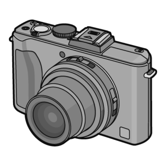
Digital Camera
Advertisement
Chapters
Table of Contents

Related Manuals for Panasonic Lumix DMC-LX5GT


Summarization of Contents
Safety Precautions
General Guidelines
General safety guidelines for servicing.
Leakage Current Checks
Procedures for cold and hot leakage current checks.
Warnings
Electrostatic Discharge Prevention (ESD)
Techniques to prevent damage from static electricity to sensitive components.
Lithium Ion Battery Recycling (US)
Information on recycling lithium-ion batteries for US customers.
Service Navigation
Introduction
Introduction to the service manual's purpose and use.
Lens Block Information
Information regarding the lens unit and optical tilt adjustment.
FeRAM Replacement Notes
Notes on replacing FeRAM and using adjustment software.
Lead Free Solder Description
Explanation of lead-free solder and its characteristics.
Model Suffix Definition
Defining Methods
Method to identify model suffixes based on nameplate markings.
Specifications
General Camera Specifications
Key technical specifications of the digital camera.
Flash and Audio Specs
Details regarding the camera's flash, microphone, and speaker.
Interface, Dimensions, and Power
Connectivity, physical dimensions, mass, and power specifications.
Location of Controls and Components
Front and Top Controls
Identification and location of front and top panel controls and indicators.
Rear and Side Controls
Identification and location of rear and side panel controls and indicators.
Body Features and Connections
Location of body features like tripod mount, speaker, doors, and connectors.
Service Mode
Error Code Memory Function
Functionality and display procedure for error code memory.
Service Fixtures and Tools
Service Fixtures and Tools
List and images of specialized tools and fixtures for servicing.
Disassembly and Assembly Instructions
Disassembly Flow Chart
Visual flowchart outlining the disassembly sequence.
PCB Location
Diagram showing the location of various PCBs within the camera.
Disassembly Procedures
Case and Body Part Removal
Steps to remove rear, front, top case units, battery door, and jack door.
PCB and Unit Removals
Steps to remove main PCB, battery PCB, gyro PCB, LVF PCB, top PCB, flash unit/PCB.
Lens Assembly Component Removal
Steps to remove lens ornament, AF/MF-Aspect FPC, battery case.
Lens Disassembly Procedure
Zoom Motor & Lens FPC Removal
Steps to remove the zoom motor and lens FPC assembly.
Lens Assembly Procedures
1st Lens Frame & Cam Alignment
Procedure for phase alignment of lens components.
1st Frame & Cam to 2nd/3rd Direct Frame Alignment
Procedure for phase alignment of lens components.
1st Frame & Cam/2nd Direct to 1st Drive Frame Alignment
Procedure for phase alignment of lens components.
1st Frame & Cam/2nd Direct/1st Drive to 2nd Lens Frame Alignment
Procedure for phase alignment of lens components.
Measurements and Adjustments
Introduction
Introduction to the measurements and adjustments section.
Pre-Disassembly Procedures
Procedures to perform before starting disassembly.
Initial Setting Release
Procedure to release initial camera settings for alignment.
Electrical Adjustment Details
Electrical Adjustment Execution
General procedure for executing electrical adjustments.
Adjustment Mode Startup
Steps to enter the electrical adjustment mode.
Status Adjustment Flag Setting
Procedure for setting and resetting adjustment status flags.
After Adjustment
Initial Setting
Procedure to perform initial settings after alignment.
Maintenance
Cleaning Lens and LCD Panel
Instructions for cleaning the lens and LCD panel.
Schematic Diagram Indications
Important Safety Notice
Safety notices related to schematic diagram indications.
Voltage Chart
Gyro PCB Voltages
Voltage chart for the Gyro PCB.
BAT PCB Voltages
Voltage chart for the Battery PCB.
Flash PCB Voltages
Voltage chart for the Flash PCB.
Top PCB Voltages
Voltage chart for the Top PCB.
Block Diagram
Overall Block Diagram
Overall block diagram of the camera system.
Schematic Diagrams
Interconnection Diagram
Diagram showing how different PCBs interconnect.
Print Circuit Board Layouts
Gyro & BAT PCB Layouts
PCB layouts for Gyro and Battery PCBs.
Top PCB Layouts
Top PCB Component Side
Component side layout of the Top PCB.
Replacement Parts List
Notes on Parts Ordering
Notes regarding ordering replacement parts.
Component Safety Notice
Safety notice regarding components marked with a delta symbol.
ESD Standards and Suppliers
ESD standards and supplier definitions for parts.
Exploded Views
Frame and Casing Section
Exploded view of the camera's frame and casing components.
Need help?
Do you have a question about the Lumix DMC-LX5GT and is the answer not in the manual?
Questions and answers