Sign In
Upload
Download
Table of Contents
Contents
Add to my manuals
Delete from my manuals
Share
URL of this page:
HTML Link:
Bookmark this page
Add
Manual will be automatically added to "My Manuals"
Print this page
×
Bookmark added
×
Added to my manuals
Manuals
Brands
Toshiba Manuals
Air Conditioner
RAS-13YKH-ES
Service manual
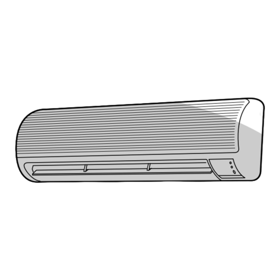
Toshiba RAS-13YKH-ES Service Manual
Split wall type air-conditioner
Hide thumbs
1
2
3
4
5
6
7
8
9
10
11
12
13
14
15
16
17
18
19
20
21
22
23
24
25
26
27
28
29
30
31
32
33
34
35
36
37
38
39
40
41
42
43
44
45
46
47
48
49
50
51
52
53
54
55
56
57
58
59
60
61
62
63
64
65
66
67
Table Of Contents
68
page
of
68
Go
/
68
Contents
Table of Contents
Troubleshooting
Bookmarks
Table of Contents
Table of Contents
Specifications
Construction Views
Indoor Unit
Outdoor Unit
Wiring Diagram
Specifications of Electrical Parts
Refrigerant Cycle Diagram
Control Block Diagram
COOL Operation
FAN ONLY Operation
Manual Setting of FAN SPEED
Operation Descriptions
DRY Operation
HEAT Operation
Louver Control
AUTO Operation
Cool Airflow Control
Temporary Auto
Cooling
Current Limit Control
Current Limit Control (Cooling)
ECONO. Mode
Cool Airflow Prevention Control
Cooling Operation
Heating Operation
High-Temperature Limit Control
Low-Temperature Limit Control
Condition to Start the Defrost Operation
Defrost Operation
Defrost Operation Time Control
Ending Condition at Defrost Operation
Auto Restart Function
How to Set the Auto Restart
When the System Is Operating
When the System Is Stand-By (Not Running)
How to Cancel the Auto Restart
In Case of Power Failure During the Timer Operation
Installation Procedure
Safety Cautions
Installation Diagram of Indoor and Outdoor Units
Air Outlet
Anchor Bolt Arrangement of Outdoor Unit
Installation
Optional Parts
Installation Parts
Others
Cutting a Hole
Indoor Unit
Mounting the Installation Plate
Remote Control
Electrical Work
When the Installation Plate Is Directly Mounted on the Wall
How to Remove the Front Cabinet
Stripping Length of Power Cord
Taking out the Power Cord
Wiring Connection
How to Connect the Connecting Cable
How to Install the Front Cabinet on the Indoor Unit
Piping and Drain Hose Installation
Stripping Length of Connecting Cable
Indoor Unit Installation
Left-Hand Connection with Piping
To Connect Pipe after Installation of Unit
Drainage
Flaring
Refrigerant Piping Connection
Required Tools for Installation Work
Tightening Connection
A5 MM Hexagon Wrench Is Required
Packed Valve Handling Precautions
Use of Vacuum Pump
Vacuum Pumping
Auto Restart Setting
Gas Leak Test
Test Operation
Misleading but Good Operations
Power Supply Voltage
Troubleshooting Chart
What to be Prechecked First
Display of Abnormalities and Judgement of the Abnormal Spots
Judgement from Defective Operation or Abnormal Operation
Primary Judgement of Trouble Sources
Role of Indoor Unit Controller
Caution of Servicing Check
How to Clear the Memory
Self-Diagnosis with Remote Control
To Release the Servicing Check
Power Can Not be Turned on
Preliminary Checks
Troubleshooting Flowcharts
Power Can Not be Turned on after Replacing Indoor P.C. Board
Outdoor Unit Does Not Operate
Only Compressor Does Not Operate
Only Outdoor Fan Does Not Operate
Only 4-Way Valve Does Not Operate (During Heating Operation)
Only the Indoor Fan Does Not Operate
How to Check the Remote Control (Including the Indoor P.C. Board)
How to Check the P.C. Board
Main P.C. Board Part
Checking Procedure
Bottom View
P.C. Board Layout
Top View
Approximate Value of the Sensor (Thermistor) Resistance
How to Reduce the Operation Time of the Anti-Restart Timer
Drain-Pan Assembly
Electrical Part Assembly
Front Panel
Part Replacement
Cross Flow Fan
Heat Exchanger
Horizontal Grille
Shaft Bearing
Common Procedure
Microcomputer
Thermal Fuse Replacement
Capacitor for Compressor
Capacitor for Fan Motor
Overload Relay
Thermostat Bimetal
Exploded Views and Parts List
Advertisement
Quick Links
1
Table of Contents
2
Specifications
3
Troubleshooting Chart
Download this manual
SERVICE MANUAL
AIR-CONDITIONER
RAS-10YKH-E / RAS-10YAH-E
RAS-13YKH-E / RAS-13YAH-E
RAS-10YKH-ES / RAS-10YAH-ES
RAS-13YKH-ES / RAS-13YAH-ES
FILE NO. DAS-SM-00-003
SPLIT WALL TYPE
Table of
Contents
Previous
Page
Next
Page
1
2
3
4
5
Advertisement
Table of Contents
Troubleshooting
Troubleshooting chart
40
Troubleshooting flowcharts
44
Need help?
Do you have a question about the RAS-13YKH-ES and is the answer not in the manual?
Ask a question
Questions and answers
Related Manuals for Toshiba RAS-13YKH-ES
Air Conditioner Toshiba RAS-10YAV-E Service Manual
Toshiba air conditioner service manual (79 pages)
Air Conditioner Toshiba RAS-10YKV-E Owner's Manual
(104 pages)
Air Conditioner Toshiba RAS-10YKV-E Service Manual
Split type (79 pages)
Air Conditioner Toshiba RAS-13YKH-E Service Manual
Split wall type air-conditioner (68 pages)
Air Conditioner Toshiba RAS-10YKH-E Service Manual
Split wall type air-conditioner (68 pages)
Air Conditioner Toshiba RAS-10GAVP-E Service Manual
Toshiba air condition service manual (116 pages)
Air Conditioner Toshiba RAS-B10SKVP-E Owner's Manual
Split type air conditioner (91 pages)
Air Conditioner Toshiba RAS-07PKVP-E Service Manual
Split type (114 pages)
Air Conditioner Toshiba RAS-10 Owner's Manual
18ufv series, 18sav series (19 pages)
Air Conditioner Toshiba RAS-10 Owner's Manual
(12 pages)
Air Conditioner Toshiba RAS-13SK-E Service Manual
Air conditioner split wall type (56 pages)
Air Conditioner Toshiba RAS-10G2KVP-E Service Manual
Split type (127 pages)
Air Conditioner Toshiba RAS-10G2KVP Series Owner's Manual
(40 pages)
Air Conditioner Toshiba RAS-13NKV-E Service Manual
(96 pages)
Air Conditioner Toshiba RAS-13BKV-E Service Manual
Split type (106 pages)
Air Conditioner Toshiba RAS- 13 Series Installation Manual
(10 pages)
Summarization of Contents
Specifications
Construction Views
Indoor Unit Construction
Detailed diagrams and dimensions for the indoor unit assembly.
Outdoor Unit Construction
Diagrams and dimensions illustrating the outdoor unit.
Wiring Diagram
Electrical Parts Specifications
Indoor Unit Electrical Parts
List of electrical components and their specifications for the indoor unit.
Outdoor Unit Electrical Parts
List of electrical components and their specifications for the outdoor unit.
Refrigerant Cycle Diagram
Control Block Diagram
Operation Descriptions
FAN ONLY Operation
Description of the FAN ONLY operating mode.
COOL Operation
Description of the COOL operating mode.
DRY Operation
Description of the DRY operating mode.
HEAT Operation
Description of the HEAT operating mode.
AUTO Operation
Automatic selection of Cooling, Fan only, or Heating mode.
ECONO. Mode
Operation mode for quiet and mild airflow with energy saving.
Current Limit Control
Controls to prevent exceeding input current limits.
High-Temperature Limit Control
Prevents condensate pressure limits during heating.
Low-Temperature Limit Control
Prevents indoor heat exchanger freezing during cooling.
Cool Airflow Prevention Control
Controls indoor fan speed to prevent cool air blow during heating.
Defrost Operation
Operation to melt ice on the outdoor heat exchanger during heating.
Auto Restart Function
Automatic unit restart after power supply interruption.
Timer Operation During Power Failure
Behavior of timer operations during power failure.
Installation Procedure
Safety Cautions
Important safety precautions for installation.
Installation Diagram
Installation
Optional Installation Parts
List of optional parts required for the installation.
Indoor Unit Installation
Cutting Hole and Mounting Plate
Instructions for preparing the wall and mounting the installation plate.
Electrical Work
Guidelines for performing electrical connections during installation.
Wiring Connection
Detailed steps for connecting the wiring of the unit.
Indoor Unit Installation Steps
Step-by-step guide to installing the indoor unit.
Drainage Installation
Instructions for proper drainage setup for the unit.
Outdoor Unit Installation Place
Guidelines for selecting the installation place for the outdoor unit.
Required Installation Tools
List of tools necessary for the installation process.
Refrigerant Piping Connection
Procedures for connecting the refrigerant piping.
Vacuum Pumping Procedure
Steps for vacuum pumping the refrigerant lines.
Outdoor Unit Wiring Connection
Final wiring connections for the outdoor unit.
Installation: Others
Miscellaneous installation-related procedures.
Troubleshooting Chart
Initial Pre-checks
Initial checks before diagnosing problems.
Power Supply Voltage Check
Checking the input power supply voltage.
Cable Connection Check
Verifying the indoor and outdoor unit cable connections.
Understanding Normal Operations
Understanding normal operations that might seem like faults.
Primary Trouble Source Judgement
Initial steps for diagnosing the source of troubles.
Indoor Unit Controller Role
Functions of the indoor unit's control system.
Abnormality Display and Judgement
Interpreting self-diagnosis codes displayed by the indoor unit.
Self-Diagnosis with Remote Control
Performing self-diagnosis using the remote control.
Clearing the Memory
Steps to clear the unit's memory.
Troubleshooting Code Table
Troubleshooting table correlating block codes with symptoms and actions.
Troubleshooting Flowcharts
Power Not Turning On
Flowchart for diagnosing power-on issues.
Outdoor Unit Not Operating
Flowchart for diagnosing outdoor unit operation failures.
Compressor Not Operating
Flowchart for diagnosing compressor-only operation failure.
Outdoor Fan Not Operating
Flowchart for diagnosing outdoor fan-only operation failure.
4-Way Valve Not Operating
Flowchart for diagnosing 4-way valve failure during heating.
Indoor Fan Not Operating
Flowchart for diagnosing indoor fan-only operation failure.
Checking Remote Control and P.C. Board
Operating Precautions
Precautions for handling the P.C. board.
Inspection Procedures
Procedures for inspecting the P.C. board.
P.C. Board Checking Procedure
Detailed checking procedures for component issues.
P.C. Board Layout
Reduce Anti-Restart Timer Operation
Part Replacement
Indoor Unit Part Replacement
Procedures for replacing parts in the indoor unit.
Microcomputer Replacement
Procedures for replacing the microcomputer and related components.
Outdoor Unit Part Replacement
Procedures for replacing parts in the outdoor unit.
Exploded Views and Parts List
Indoor Unit Parts (1)
Exploded view and parts list for the indoor unit.
Indoor Unit Parts (2)
Second part of the indoor unit exploded view and parts list.
Outdoor Unit Exploded View and Parts
Exploded view and parts list for the outdoor unit.
Table of Contents
Save PDF
Print
Rename the bookmark
Delete bookmark?
Delete from my manuals?
Login
Sign In
OR
Sign in with Facebook
Sign in with Google
Upload manual
Upload from disk
Upload from URL
Need help?
Do you have a question about the RAS-13YKH-ES and is the answer not in the manual?
Questions and answers