
Related Manuals for GE Spacemaker JNM1951


Summarization of Contents
IMPORTANT SAFETY NOTICE
RECONNECT ALL GROUNDING DEVICES
Proper reattachment of grounding devices after servicing.
PRECAUTIONS TO AVOID POSSIBLE EXPOSURE TO EXCESSIVE MICROWAVE ENERGY
Safety measures to prevent microwave energy exposure during servicing.
Nomenclature
Model Number
Explanation of the model number format and its components.
Serial Number
Explanation of the serial number format and its components.
Introduction
Features and Benefits
Overview of the microwave oven's key features and advantages.
Control Features
PVM2170 Features
Specific features and controls for the PVM2170 model.
Power Saver Feature
Explanation of the power saving feature and its operation.
PVM2170 Controls
Cooking Controls
Details on operating cooking functions and timers.
Convenience Features
Explains how to use specific convenience cooking options.
DVM1950, JVM1950, JNM1951 Features
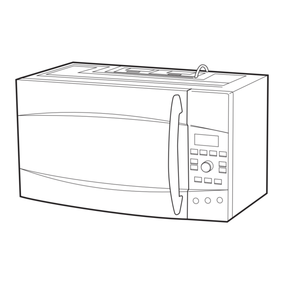
Features of the Oven
Identifies and describes the main physical features of the oven.
DVM1950, JVM1950, JNM1951 Controls
Cooking Controls
Details on operating cooking functions and timers for specific models.
Convenience Features
Explains how to use specific convenience cooking options for specific models.
PVM1970, PNM1971 Features
Features of the Oven
Identifies and describes the main physical features of the oven.
PVM1970, PNM1971 Controls
Cooking Controls
Details on operating cooking functions and timers for specific models.
Convenience Features
Explains how to use specific convenience cooking options for specific models.
MyPlate.gov Feature
MyPlate.gov Usage
Instructions for using the MyPlate.gov feature across various models.
Cooking Guide for MyPlate.gov
Food Groups and Types
Lists food groups, types, and serving suggestions for MyPlate.gov.
Sensor Cooking Notes
Important notes and recommendations for optimal sensor cooking results.
Component Locator Views
Front View
Diagrams showing component locations from the front view.
Front View – Control Panel Assembly Removed
Diagrams showing component locations after control panel removal.
Right Side View
View From Right Side
Diagrams showing component locations from the right side view.
View From Top Right Side
Diagrams showing component locations from the top right side view.
Circuit Board Connectors View
PVM2170 Smart Board
Diagram of the PVM2170 smart board connectors.
PVM2170 Display Board
Diagram of the PVM2170 display board connectors.
Components
Electrical Terminal Release/Locking Tab
Illustration and explanation of electrical terminal locking tabs.
Microwave Oven Removal
Step-by-step instructions for removing the microwave oven unit.
Grille Assembly
Instructions on how to remove and reinstall the grille assembly.
Outer Cover
To remove the outer cover
Detailed steps for removing the outer cover of the microwave oven.
Door Assembly
Door Assembly Removal
Step-by-step procedure for removing the microwave oven door assembly.
To disassemble the door
Interior Light
Information about the interior light and how to remove it.
Power Saver (Energy Saver)
Power Saver Operation
Explanation of the power saver feature, its recommendations, and limitations.
Power Saver Battery
Stirrer Assembly
Description and removal instructions for the stirrer assembly.
Line Fuse
To remove the fuse
Detailed steps for removing the line fuse.
High Voltage Fuse
High Voltage Transformer Fuse
Information about the high voltage fuse and its location.
Noise Filter
Noise Filter Function and Checks
Explanation of the noise filter and its resistance measurement.
Vent Blower
To remove the vent blower
Instructions for removing the vent blower assembly from the unit.
Control Panel Assembly
To remove the control panel assembly
Step-by-step guide for removing the control panel assembly.
Door Interlock Switches
Door Sensing and Primary Interlock Switches
Description of door sensing and primary interlock switch functions.
Monitor Switch
Explanation of the monitor switch function and its operation.
Functions
Describes the state of switches when the door is opened and closed.
To remove the door interlock switches
Smart Board
Instructions for removing the smart board from the unit.
Display Board
To remove the display board
Steps for removing the display board.
Bottom Thermal Cut Out (TCO)
To remove the bottom TCO
Instructions for removing the bottom thermal cut out.
Turntable Coupling
Turntable Motor
Location and removal instructions for the turntable motor.
Surface Lamps
To remove surface lamp assemblies
Steps for removing and replacing the surface lamp assemblies.
Magnetron Thermal Cut Out (TCO)
To remove the magnetron TCO
Instructions for removing the magnetron thermal cut out.
Magnetron
To remove the magnetron
Step-by-step procedure for removing the magnetron from the oven.
Vent Fan Motor Capacitor
To remove the vent fan motor capacitor
Instructions for removing the vent fan motor capacitor.
Cavity Thermal Cut Out (TCO)
To remove the cavity TCO
Instructions for removing the cavity thermal cut out.
Vent Thermal Cut Out (TCO)
To remove the vent TCO
Instructions for removing the vent thermal cut out.
Cooling Fan Motor
To remove the cooling fan motor
Step-by-step guide for removing the cooling fan motor.
Capacitor and Diode
To remove the capacitor and diode
Instructions for removing the high voltage capacitor and diode.
High Voltage Transformer
To remove the high voltage transformer
Step-by-step procedure for removing the high voltage transformer.
Demo Mode
To enter Demo Mode
Instructions for entering Demo Mode for different microwave models.
Troubleshooting
Troubleshooting Flowchart
A flowchart to diagnose and resolve common microwave issues.
Oven Performance Test
Oven Performance Test Procedure
Steps to conduct an oven performance test using water.
Microwave Leakage Test
Microwave Leakage Test Procedure
Steps for performing a microwave leakage test.
Error Messages
Error Message Descriptions
List and explanation of displayed error messages.
Control Performance Test
Control Performance Test Procedure
Steps to test the functionality of control panel pads.
Technical Data Sheet
Smart Board Connectors
Information on smart board connectors and their pin/voltage assignments.
Door Interlocks (Door Latch Switches)
To test the door interlocks
Procedure to test the continuity of door interlock switches.
Monitor Switch
Testing procedure for the monitor switch.
Main Fuse
Warning and replacement information related to the main fuse.
Sensor
Sensor Cooking Test
Procedure for testing the sensor cooking function with ground meat.
Sensor Test (Quick Test)
Quick diagnostic test for the sensor and its possible failure modes.
Key Panel Test
Key Panel Test Procedure
Steps to verify key panel pad continuity using a ribbon cable.
Schematics and Wiring Diagrams
PVM2170 Schematic Diagram
Detailed schematic diagram for the PVM2170 model.
PVM2170 Wiring Diagram
PVM2170 Wiring Diagram Details
Detailed wiring diagram for the PVM2170 model, showing harness leads.
DVM1950, JNM1951, JVM1950, PVM1970, PNM1971 Schematic Diagram
Schematic Diagram Explanation
Schematic diagram covering multiple models with component connections.
DVM1950, JNM1951, JVM1950, PVM1970, PNM1971 Wiring Diagram
Wiring Diagram Details
Wiring diagram for multiple models showing component connections and leads.
High Voltage Half-Wave Doubler
Circuit Operation
Explanation of the high voltage half-wave doubler circuit operation.
Warranty
GE Will Replace
Details on what GE will replace under the warranty terms.
What GE Will Not Cover
List of exclusions from the GE warranty coverage.
Need help?
Do you have a question about the Spacemaker JNM1951 and is the answer not in the manual?
Questions and answers