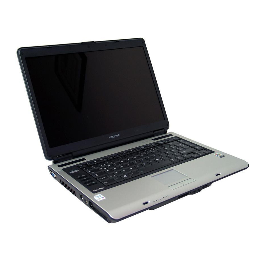
Toshiba Satellite A105 Series Maintenance Manual
Toshiba personal computer
Hide thumbs
Also See for Satellite A105 Series:
- Maintenance manual (294 pages) ,
- User manual (289 pages) ,
- Resource manual (72 pages)

Related Manuals for Toshiba Satellite A105 Series


Summarization of Contents
Chapter 1 Hardware Overview
1.1 Features
Details the key features and specifications of the Toshiba Satellite A100/A105 and Tecra A7.
1.2 System Unit Components
Describes the various internal components and their functions within the system unit.
1.7 Power Supply
Explains the functions and operation of the computer's power supply unit.
Chapter 2 Troubleshooting
2.2 Basic Flowchart
Provides a step-by-step visual guide for diagnosing common FRU failures.
2.3 Power Supply
Details troubleshooting procedures for power supply related issues.
2.4 System Board
Outlines troubleshooting steps for diagnosing system board defects.
2.5 2.5-inch HDD
Provides procedures for troubleshooting issues with the 2.5-inch Hard Disk Drive.
2.11 Finger Print(Optional)
Describes troubleshooting steps for the optional fingerprint reader.
Chapter 3 Diagnostic Programs
3.1 General
Introduces the diagnostic programs and their classification.
3.2 Quick Start
Explains how to perform basic diagnostic tests and run test items.
3.3 Options
Details how to configure batch parameters and test item settings.
3.5 System Test
Covers diagnostic tests for CPU, Coprocessor, and Boards.
3.11 Error Codes and description
Lists and explains common error codes encountered during diagnostics.
Chapter 4 Replacement Procedures
4.1 General
Provides an overview of disassembly, FRU identification, and safety precautions.
4.2 HDD
Details the procedures for removing and installing the Hard Disk Drive.
4.9 CPU Cooling Module and Fan
Explains the steps for removing and installing the CPU cooling module and fan.
4.11 CPU
Provides instructions for removing and installing the Central Processing Unit (CPU).
4.13 System Board, USB Board, AC-IN cable
Details the procedures for removing and installing the system board and related cables.
4.16 LCD Module
Explains the steps for removing and installing the LCD module.
Appendices
Appendix A Handling the LCD Module
Offers precautions and guidelines for safely handling the LCD module.
Appendix B Board Layout
Illustrates the physical layout of system board components and connectors.
Appendix C Pin Assignments
Provides detailed pin assignment information for various system connectors.
Need help?
Do you have a question about the Satellite A105 Series and is the answer not in the manual?
Questions and answers