Table of Contents
Advertisement
Quick Links
SERVICE MANUAL
MODEL
COMMANDER
KV-HS29M61
RM-997
KV-HS29M90
RM-997
KV-HS29M91
RM-997
KV-HS34M61
RM-997
KV-HS34M61
RM-997
KV-HS34M90
RM-997
DEST. CHASSIS NO.
ES
SCC-M03-A
HK
SCC-P96-C
ME
SCC-P98-C
GE
SCC-P97-A
S
SCC-M01-A
HK
SCC-P96-A
VIDEO
DRC-MF
A/B
V CENTER
HD/DVD
1
2
3
4
5
6
7
8
9
0
JUMP
PROG
OPTION
RESET
TV
RM-997
AG-3F
MODEL
COMMANDER
KV-HS34M91
RM-997
KV-HS38M61
RM-997
KV-HS38M61
RM-997
KV-HS38M90
RM-997
KV-HS38M91
RM-997
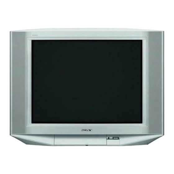
KP-HS29M61/M90/M91,
KP-HS34M61/M90/M91,
KP-HS38M61/M90/M91
TRINITRON
DEST. CHASSIS NO.
ME
SCC-P98-A
GE
SCC-P97-B
S
SCC-M01-B
HK
SCC-P96-B
ME
SCC-P98-B
COLOR TV
®
Advertisement
Table of Contents

Summarization of Contents
SELF DIAGNOSTIC FUNCTION
Diagnostic Test Indicators
Identifying probable causes of errors via STANDBY/TIMER lamp flashes.
Display of Standby/Timer Light Flash Count
Visual representation of STANDBY/TIMER lamp flash counts.
Stopping the Standby/Timer Flash
Procedure to stop the STANDBY/TIMER lamp from flashing.
Self-Diagnostic Screen Display
Displaying diagnostic results on the screen.
Handling of Self-Diagnostic Screen Display
Managing and clearing diagnostic screen results.
Self-Diagnostic Circuit
Explanation of the self-diagnostic circuit operation.
DISASSEMBLY
Rear Cover Removal
Procedure for removing the television's rear cover.
Speaker Box Removal
Steps for detaching the speaker box assembly.
Chassis Assembly Removal
Instructions for removing the main chassis assembly.
Service Position
Setting the TV to a service position for access.
DC Board Removal
Steps for removing the DC board.
J Board Removal
Procedure for detaching the J board.
D Board Removal
Instructions for removing the D board.
A, A1, V2, E Boards and B4 Block Removal
Steps for removing multiple boards and the B4 block.
H1, H2, MS2, F2 Boards Removal
Procedure for removing H1, H2, MS2, and F2 boards.
Picture Tube Removal (Part 1)
Initial steps for removing the picture tube assembly.
Picture Tube Removal (Part 2)
Subsequent steps for removing the picture tube.
Harness Rerouting
Details on routing harnesses during service.
SET-UP ADJUSTMENTS
Beam Landing Adjustment
Adjusting beam landing for optimal picture geometry.
Convergence Adjustment
Correcting color convergence for an aligned image.
Focus Adjustment
Adjusting the picture focus for sharpness.
Neck Assembly Twist Adjustment
Adjusting neck assembly twist for proper alignment.
G2 (Screen) and White Balance Adjustments
Setting G2 voltage and balancing white colors.
CIRCUIT ADJUSTMENTS
Adjustments with Commander
Performing adjustments using the remote commander.
Adjustment Method
General procedure for circuit adjustments.
Picture Quality Adjustments
Adjusting parameters to optimize picture quality.
Picture Quality Adjustment Preparation
Steps to prepare for picture quality adjustments.
NTSC Video Input Adjustments
Adjustments for NTSC video input signals.
NTSC RF Input Adjustments
Adjustments for NTSC RF input signals.
PAL Video Input Adjustments
Adjustments for PAL video input signals.
PAL RF Input Adjustments
Adjustments for PAL RF input signals.
SAFETY RELATED ADJUSTMENTS
HV Regulation Adjustment
Adjusting the high voltage regulation circuit.
HV Hold-down Adjustment
Adjusting the HV hold-down circuit.
HV Protector Adjustment
Adjusting HV protector circuit parameters.
HV Protector Check
Verifying HV protector functionality.
+B Max Voltage Confirmation
Confirming the maximum +B voltage level.
+B OVP Confirmation
Confirming the +B overvoltage protection.
DIAGRAMS
Block Diagrams
Overall functional block diagrams of the TV system.
Circuit Boards Location
Visual guide to the location of internal circuit boards.
Schematic Diagrams
Detailed electronic schematics for various circuit boards.
Semiconductors
List and diagrams of semiconductor components.
EXPLODED VIEWS
Picture Tube Exploded View
Diagram showing the picture tube and its components.
Chassis Exploded View
Diagram illustrating the chassis and its parts.
Packing Materials List
List of packing materials used for shipping the product.


Need help?
Do you have a question about the Trinitron KV-HS38M61 and is the answer not in the manual?
Questions and answers