Table of Contents
Advertisement
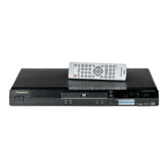
DVD PLAYER
DV-454-K
DV-454-S
THIS MANUAL IS APPLICABLE TO THE FOLLOWING MODEL(S) AND TYPE(S).
Model
DV-454-K
WYXU
DV-454-K
WYXU/FRGR
DV-454-K
WVXU
DV-454-S
WYXU
DV-454-S
WYXU/FRGR
DV-454-S
WVXU
Confirm it
Serial No.
For details, refer to "Important symbols for good services".
PIONEER CORPORATION
PIONEER ELECTRONICS (USA) INC. P.O. Box 1760, Long Beach, CA 90801-1760, U.S.A.
PIONEER EUROPE NV Haven 1087, Keetberglaan 1, 9120 Melsele, Belgium
PIONEER ELECTRONICS ASIACENTRE PTE. LTD. 253 Alexandra Road, #04-01, Singapore 159936
PIONEER CORPORATION 2002
STANDBY/ON
Type
Power Requirement
AC220-240V
AC220-240V
AC220-240V
AC220-240V
AC220-240V
AC220-240V
4-1, Meguro 1-chome, Meguro-ku, Tokyo 153-8654, Japan
OPEN/
CLOSE
0
1
¡
3
Î
4
¢
7
8
DV-454-K
Regional restriction
codes (Region No.)
2
2
2
2
2
2
T – ZZE MAY 2002 Printed in Japan
ORDER NO.
RRV2610
Remarks
Advertisement
Table of Contents

Summarization of Contents
Safety Information
Laser Diode Characteristics and Cautions
Details laser specifications and safety precautions for operation.
Important Symbols for Good Services
Product Safety
Emphasizes conforming to regulations and following safety instructions during servicing.
Adjustments
Highlights the importance of optimum adjustments for product performance.
Cleaning
Stresses proper cleaning of optical pickups and lenses for performance.
Shipping Mode and Shipping Screws
Advises setting shipping mode or screws to protect from transit damage.
Lubricants, Glues, and Replacement Parts
Guides on appropriate application of lubricants/glues and use of prescribed parts.
1. Specifications
General Specifications
Details system, power, weight, dimensions, operating temp/humidity.
Output Specifications
Covers video, audio, and digital output characteristics.
Accessories Included
Lists all accessories provided with the player.
2. Exploded Views and Parts List
2.1 Packing Details
Illustrates the packaging contents and assembly.
2.2 Exterior Section Overview
Provides an exploded view of the player's external components.
Exterior Parts List and Contrast
Lists external parts and compares them across models.
2.3 Loading Mechanism Assembly
Shows the exploded view and components of the disc loading mechanism.
Loading Mechanism Parts List
Lists all parts for the loading mechanism assembly.
Lubrication Points for Mechanism
Details specific locations for applying lubricant to mechanism parts.
2.4 Traverse Mechanism Assy-S
Illustrates the traverse mechanism components and assembly.
Traverse Mechanism Parts List
Lists all parts for the traverse mechanism assembly.
3. Block Diagram and Schematic Diagram
3.1 Block Diagram Overview
Presents a high-level circuit overview and signal paths.
3.1.2 Power Supply Block
Details the power distribution and regulation within the player.
3.1.3 Waveforms
Displays oscilloscope waveforms for key test points.
3.2 Loab Assy and Wiring Diagram
Shows the LOAB Assy and the system's overall wiring diagram.
3.3 FJMB Assy 1/5 [Front End Block]
Details the front-end circuitry of the FJMB assembly.
3.4 FJMB Assy 2/5 [Back End Block]
Details the back-end circuitry of the FJMB assembly.
3.5 FJMB Assy 3/5 [Audio Block]
Details the audio processing circuitry of the FJMB assembly.
3.6 FJMB Assy 4/5 [Video Block]
Details the video processing circuitry of the FJMB assembly.
3.7 FJMB Assy 5/5 [FL Control Block]
Details the FL display control circuitry of the FJMB assembly.
3.8 IRKY and PSWB Assemblies
Explains the IRKY and PSWB assemblies, likely for remote and power control.
3.9 Power Supply Unit (VWR1352) Schematic
Provides the schematic for the VWR1352 power supply unit.
3.10 Power Supply Unit (VWR1354) Schematic
Provides the schematic for the VWR1354 power supply unit.
3.11 SCRB Assy Schematic
Shows the schematic for the SCRB assembly.
4. PCB Connection Diagram
4.1 LOAB Assy PCB Layout
Illustrates the PCB layout and connections for the LOAB assembly.
4.2 FJMB Assy PCB Layout
Shows the PCB layout and component placement for the FJMB assembly.
4.3 IRKY and PSWB Assy PCB Layouts
Details the PCB layouts for the IRKY and PSWB assemblies.
4.4 Power Supply Unit (VWR1352) PCB Layout
Illustrates the PCB layout for the VWR1352 power supply unit.
4.5 Power Supply Unit (VWR1354) PCB Layout
Illustrates the PCB layout for the VWR1354 power supply unit.
4.6 SCRB Assy PCB Layouts
Shows the PCB layouts for the SCRB assembly (Side A and Side B).
5. PCB Parts List
List of Assemblies
Lists major assemblies and their part numbers.
Component Parts Lists
Lists semiconductors, capacitors, resistors, and other components with part numbers.
6. Adjustment
6.1 Adjustment Items and Location
Identifies adjustable points and necessary procedures for mechanism adjustment.
6.2 Jigs and Measuring Instruments
Lists required tools and test equipment for adjustments.
6.3 Necessary Adjustment Points
Details specific adjustment points required after replacing key mechanism parts.
6.4 Test Mode Operations
Explains how to enter, operate, and exit the player's test mode.
6.5 Mechanism Adjustment Procedures
Describes the procedure for tangential and radial height coarse adjustment.
DVD Jitter Adjustment Process
Details the process for adjusting the DVD jitter to its minimum value.
Initialize Focus Sweep Setting
Explains how to set the focus sweep correctly after mechanism replacement.
7. General Information
7.1 Diagnosis and Troubleshooting
Covers diagnostic procedures, test modes, error history, and troubleshooting.
7.2 IC Information
Lists key ICs and their functions.
7.3 Cleaning Procedures
Provides instructions for cleaning the pickup lenses.
8. Panel Facilities
Front Panel Controls
Identifies and describes the controls on the player's front panel.
Front Panel Display Indicators
Explains the meaning of various indicators on the player's front panel display.
Rear Panel Connections Guide
Details all the input and output connectors on the rear panel.
Remote Control Functions Overview
Describes the purpose and operation of each button on the remote control.
Remote Control Functions Detailed
Continues the explanation of remote control buttons and their functions.


Need help?
Do you have a question about the DV-454-S and is the answer not in the manual?
Questions and answers