Table of Contents
Advertisement
SERVICE MANUAL
Ver 2-2004E
Revision History
Area
Model
VGN-A50B
VGN-A60B
VGN-A60PS*
Japanese
Japanese
VGN-A60S*
VGN-A70P
VGN-A70PS*
VGN-A70S*
VGN-A130*
VGN-A130P*
US
American
VGN-A170*
Canadian
VGN-A170P*
VGN-A190
VGN-A115B
VGN-A115S
VGN-A117S
AEP
European
VGN-A195EP
UK
VGN-A195HP
VGN-A197VP
VGN-A197XP
VGN-A15GP
International
VGN-A17GP
Thai
VGN-A17SP
Asian/Oceania/
South Africa
9-876-367-02
Line up
[MA]
1
[MA]
1
[MA]
1
[MA]
1
[MA]
1
[MA]
1
[MA]
1
[MA]
1
[MA]
1
[MA]
1
[MA]
1
*: CTO Model
VGN-A50B/A60B/A60PS/A60S/A70P/A70PS/A70S
VGN-A115B/A115S/A117S/A195EP/A195HP/A197VP/A197XP
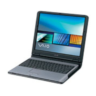
Illust : VGN-A70P
VGN-A130/A130P/A170/A170P/A190
VGN-A15GP/A17GP/A17SP
• Design and specifications are subject to
change without notice.
•
PERSONAL COMPUTER
S400
Advertisement
Table of Contents

Related Manuals for Sony VAIO VGN-A190


Summarization of Contents
Service and Inspection Precautions
Obey precautionary markings and instructions
Observe safety labels and markings on equipment and in documentation.
Use designated parts only
Use only specified parts for safety and performance.
Follow original design for mounting and wiring
Replicate original layout and wiring to preserve safety features.
Inspect after completing service
Verify correct reassembly and check for damage after service.
Replacing chip components
Avoid reusing components; handle tantalum capacitors carefully.
Handling flexible print boards
Follow specific temperature and handling guidelines for flexible PCBs.
CHAPTER 1. SPECIFICATIONS
1-1. Specifications
Detailed technical specifications for various VGN-A series models.
1-2. CTO Information
Information on Customer-Tailored Options (CTO) for specific models.
CHAPTER 2. BLOCK DIAGRAM
2-1. VGN-A series
Block diagram of the main unit's internal architecture.
2-2. Port Replicator (VGP-PRAV1)
Block diagram for the VGP-PRAV1 port replicator.
CHAPTER 3. FRAME HARNESS DIAGRAM
3-1. VGN-A series
Frame harness diagram for the main VGN-A series unit.
3-2. Port Replicator (VGP-PRAV1)
Frame harness diagram for the VGP-PRAV1 port replicator.
CHAPTER 4. EXPLODED VIEWS AND PARTS LIST
Palmrest
Exploded views and parts list for the palmrest assembly.
Main Board
Exploded views and parts list for the main board.
Bottom
Exploded views and parts list for the bottom case.
Optical Drive
Exploded views and parts list for optical drive options.
LCD
Exploded views and parts list for LCD panel assemblies.
Accessories
Lists various accessories like power cords, adapters, and cables.
DIP Switch
Configuration settings via DIP switches.
CHAPTER 5. OTHERS
5-1. The Barcode Label
Information on locating and understanding barcode labels on components.
5-2. Replacing the CPU
Step-by-step instructions for removing and installing the CPU.
Need help?
Do you have a question about the VAIO VGN-A190 and is the answer not in the manual?
Questions and answers