Table of Contents
Advertisement
This document is printed on chlorine free (ECF) paper.
PA
011869
MG166CX-USB/MG166CX: xxxxxx-xxxxx
MG166C-USB/MG166C: xxxxxx-xxxxx
SERVICE MANUAL
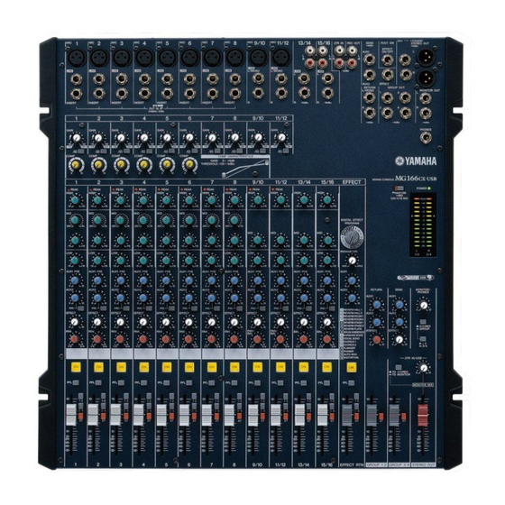
MG166CX-USB
I CONTENTS
SPECIFICATIONS
.............................................................................. 7
.......................................................................... 44/52
IC & DIODE FIGURES
BLOCK & LEVEL DIAGRAM
Copyright (c) Yamaha Corporation. All rights reserved.
.................................................................. 3/5
......................................................... 8
.................................. 12
............................................................. 13
........................................ 14
..................................................... 19
.......................................................... 23
.................................................. 27
...................................................... 30
........................................................... 33
HAMAMATSU, JAPAN
MG166C-USB
07.08
Advertisement
Table of Contents

Related Manuals for Yamaha MG 166C-USB


Summarization of Contents
Specifications
Electrical Specifications
Detailed electrical characteristics and performance parameters of the mixing console.
General Specifications
General specifications for the mixing console, including dimensions and power requirements.
Panel Layout
Channel Control Section
Details the layout and function of controls on the channel strip for audio adjustments.
Digital Effects Section
Explains the controls for the built-in digital effects unit, including program selection and parameter adjustment.
Master Control Section
Describes the master section controls for overall sound mixing, monitoring, and output routing.
Overall Assembly Wiring
Inner Chassis Assembly Wiring
Details the internal chassis wiring procedures to prevent panel lifting during assembly.
MG166CX-USB/MG166CX Disassembly Procedures
Top Cover Disassembly
Instructions for removing the top cover, including fader knobs and screws.
MG166C-USB/MG166C Disassembly Procedures
Top Cover Disassembly
Instructions for removing the top cover, including fader knobs and screws for specific models.
LSI Pin Description
AK5381VT-E2 ADC Pin Description
Details the pin configuration and functions of the AK5381VT-E2 Analog to Digital Converter IC.
PCM1742KEG/2K DAC Pin Description
Outlines the pin assignments and functions for the PCM1742KEG/2K Digital to Analog Converter IC.
PCM2900E/2K CODEC Pin Description
Lists the pin functions for the PCM2900E/2K CODEC IC, including USB interface details.
MX23L8103TC-90G CPU Pin Description
Describes the pin configurations and functions of the MX23L8103TC-90G CPU IC.
IC Block Diagram
NJM2068M-D Op-Amp Block Diagram
Shows the internal block diagram of the NJM2068M-D Dual Operational Amplifier.
KIA7812API Regulator Block Diagram
Illustrates the block diagram for the KIA7812API +12V voltage regulator.
NJM072BM-E Op-Amp Block Diagram
Presents the block diagram for the NJM072BM-E Dual Operational Amplifier.
PST596DNR System Reset Block Diagram
Depicts the block diagram for the PST596DNR System Reset IC.
Circuit Boards
DSP Circuit Board Layout
Diagram showing the component layout of the DSP circuit board.
PS16X/PS16 Circuit Board Layout
Shows the component layout of the PS16X/PS16 circuit board.
USB Circuit Board Layout
Diagram illustrating the component placement on the USB circuit board.
JACK16X/JACK16 Circuit Board Layout
Illustration of the component placement on the JACK16X/JACK16 circuit board.
MIX16X/MIX16 Circuit Board Layout
Diagram detailing the component layout for the MIX16X/MIX16 circuit board.
Inspections
Measurement Conditions
Specifies the environmental conditions and power source requirements for performing tests.
Mixer Check
Details the preparation steps for checking mixer functions, including load resistances and control settings.
Parts List
Parts List Contents
Table of contents for the parts list, detailing various assemblies and their corresponding pages.
Destination Abbreviations
Explains the abbreviations used for different destination models (e.g., U.S.A., European).
Parts List Warnings
Provides critical warnings and notes regarding special parts and their specifications.
Need help?
Do you have a question about the MG 166C-USB and is the answer not in the manual?
Questions and answers