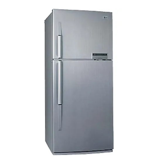
Table of Contents
Troubleshooting

Summarization of Contents
SERVICING PRECAUTIONS
Air Recharging in Compressor
Details the process for recharging refrigerant into the compressor system.
3. DISASSEMBLY
3-1 DOOR
Procedures for disassembling freezer and refrigerator doors.
3-2 DOOR SWITCH
Steps to remove and disconnect the door switch.
3-3 FAN AND FAN MOTOR
Instructions for removing the fan and motor assembly.
3-4 DEF' CONTROL ASSY
Guide for removing the defrost control assembly.
3-5 LAMP
Steps for replacing freezer and refrigerator room lamps.
3-6 DUCT, MULTI-R
Procedure for removing the multi-flow duct and control box.
4. ADJUSTMENT
4-1 COMPRESSOR
Explains compressor composition, role, and notes for use.
4-2 PTC-STARTER
Details the PTC starter's composition, role, and usage precautions.
4-3 OLP (OVER LOAD PROTECTOR)
Defines and explains the role of the Over Load Protector.
6. TROUBLESHOOTING
6-1 COMPRESSOR AND ELECTRIC COMPONENTS
Troubleshooting steps for compressor and related electric components.
6-2 PTC AND OLP
Troubleshooting steps for PTC and OLP components.
6-3 ANOTHER ELECTRIC COMPONENTS
Troubleshooting for other electric components affecting cooling.
6-4 SERVICE DIAGNOSIS CHART
A chart to diagnose common refrigerator complaints and their remedies.
6-5 REFRIGERATING CYCLE
Troubleshooting chart for issues related to the refrigerating cycle.
7. DESCRIPTION OF FUNCTION & CIRCUIT OF MICOM
7-1 FUNCTION
Explains the basic functions and operation of the MICOM system.
7-2 PCB FUNCTION
Details various circuits within the Printed Circuit Board (PCB).
7-3 RESISTANCE SPECIFICATION OF SENSOR
Lists resistance specifications for temperature sensors.
7-4 TROUBLE SHOOTING
Provides troubleshooting steps for common refrigerator issues.
7-5 MAIN PWB ASS'Y AND PARTS LIST
7-5-1 MAIN PWB ASS'Y
Diagram of the main PWB assembly.
7-5-2 MAIN PWB ASS'Y
Diagram of the main PWB assembly for different models.
7-5-3 REPLACEMENT PARTS LIST
List of replacement parts for GR-R562/R602.
7-5-4 REPLACEMENT PARTS LIST
List of replacement parts for GR-S562/S602.
7-5-5 PWB ASS'Y, DISPLAY AND PARTS LIST
PWB and display assembly with parts list.
7-5-6 PWB ASS'Y, DISPLAY AND PARTS LIST
PWB and display assembly with parts list for other models.
7-6 PWB DIAGRAM
7-6-1 PWB DIAGRAM
Schematic diagram of the main PWB for GR-R562/R602.
7-6-2 PWB DIAGRAM
Schematic diagram of the main PWB for GR-S562/S602.
8. EXPLODED VIEW & REPLACEMENT PARTS LIST
8-1.
Exploded views of refrigerator parts for different models.


Need help?
Do you have a question about the GR-R491JTA and is the answer not in the manual?
Questions and answers