Table of Contents
Advertisement
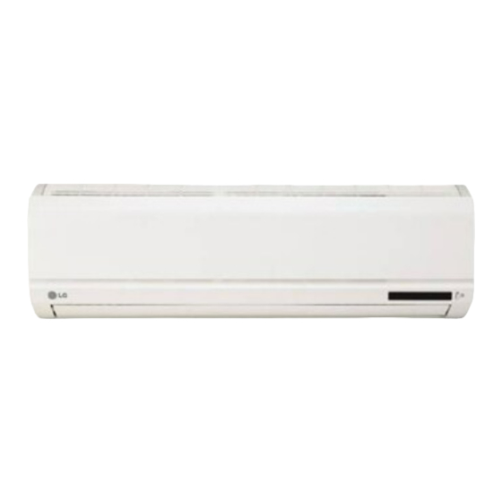
Room Air Conditioner
SVC MANUAL(Exploded View)
MODELS: S092CG
S122CG
S122HG
S182CG
S182HG
S242CG
S242HG
S092CG
S242CG
S182CG
G122C
CAUTION
Before Servicing the unit, read the safety precautions in General SVC manual.
Only for authorized service personnel.
S092CG
N40
U40
S122CG
N40
U40
S122HG
N40
U40
S182CG
N50
U50
S182HG
N50
U50
S242CG
N50
U50
S242HG
N50
U50
S092CG
N41
U41
S242CG
N51
U51
S182CG
N51
U51
SR2
Internal Use Only
http://biz.lgservice.com
S092CG
S092CP
S41
S122CG
S122CP
S41
S122HG
S41
S182CG
S182CP
S52
S182HG
S51
S242CG
S242CP
S51
S242HG
S51
S122DC
S122DC
S40
S122DP
S122DP
S41
S122DH
S122DH
S40
S182DP
S182DP
S52
S182GP
S182GP
S52
S41
S41
S52
S51
S40
S41
S40
S52
S52
Advertisement
Table of Contents

Summarization of Contents
Safety Precautions
Installation Safety
Covers warnings and precautions for unit installation.
Operation Safety
Covers warnings and precautions for unit operation.
Dimensions
Indoor Unit Dimensions
Physical measurements and diagrams for indoor units.
Outdoor Unit Dimensions
Physical measurements and diagrams for outdoor units.
Installation Procedures
Selecting the Best Location
Guidelines for choosing optimal indoor and outdoor unit placement.
Piping and Drainage Installation
Steps for mounting plates, drilling walls, and connecting drain hoses.
Piping Connection Procedures
Flaring Work and Burr Removal
Detailed steps for preparing refrigerant pipes.
Indoor Piping Connection
Connecting pipes to the indoor unit and routing them.
Outdoor Piping Connection
Connecting pipes to the outdoor unit service valves.
Electrical Wiring
Connecting Indoor Unit Cable
Connecting the power and communication cables to the indoor unit.
Connecting Outdoor Unit Cable
Connecting the power cable to the outdoor unit control board.
Drainage and Piping Formation
Checking Drainage
Verifying proper water flow from the indoor unit.
Forming and Insulating Piping
Securing and insulating refrigerant pipes and hoses.
Air Purging and Evacuation
Leak Testing Procedure
Methods to check for refrigerant leaks using nitrogen or soap.
Evacuation Procedure
Using a vacuum pump to remove air and moisture.
Test Running Procedures
Outdoor Unit Settlement
Anchoring the outdoor unit securely to its mount.
Performance Evaluation
Checking air temperature difference and refrigerant charge.
Pump Down Procedure
Collecting refrigerant for relocation or service.
Operation Modes and Functions
Display Indicators and Signals
Explains the meaning of operation and indicator lights.
Self-Diagnosis Function
Explains error codes and troubleshooting checks.
Remote Control Operations
Detailed explanation of the remote control buttons and functions.
Indoor Unit Disassembly
Grille and Control Box Removal
Steps to access internal components.
Evaporator and Fan Assembly Removal
Steps for removing key internal parts like the evaporator and fan.
Schematic and Wiring Diagrams
Electric Control Device Diagram
Circuit diagram for the main control board.
Unit Wiring Diagrams
Wiring schematics for indoor and outdoor units.
Components Location
Identifies components on the main PCB.
Troubleshooting Guide
Refrigeration Cycle Diagrams
Visual representation of refrigerant flow for different models.
Valve Operation and Refrigerant Handling
Guidance on using service valves and procedures like pumping down.
Trouble Analysis by Symptoms
Diagnosing issues based on temperature and pressure readings.
Electronic Part Troubleshooting
Steps for diagnosing and fixing electronic component issues.
Component Specific Troubleshooting
Fault finding for compressor, fans, and louvers.
Exploded Views and Part Numbers
Indoor Unit Exploded Views
Diagrams showing disassembled parts of the indoor unit.
Outdoor Unit Exploded Views
Diagrams showing disassembled parts of the outdoor unit.


Need help?
Do you have a question about the S122CG and is the answer not in the manual?
Questions and answers