Table of Contents
Advertisement
SERVICE MANUAL
Ver. 1.1 2009.11
• The tuner and CD sections have no adjustments.
Tuner section
FM
Tuning range:
Except Saudi Arabia model:
87.5 – 108.0 MHz (at 50 kHz step)
87.5 – 107.9 MHz (at 200 kHz step)
Saudi Arabia model:
87.5 – 108.0 MHz
FM tuning interval:
Except Saudi Arabia model:
50 kHz/200 kHz switchable
Antenna (aerial) terminal:
External antenna (aerial) connector
Intermediate frequency: 150 kHz
Usable sensitivity: 10 dBf
Selectivity: 75 dB at 400 kHz
Signal-to-noise ratio: 70 dB (mono)
Separation: 40 dB at 1 kHz
Frequency response: 20 – 15,000 Hz
AM
Tuning range:
Except Saudi Arabia model:
531 – 1,602 kHz (at 9 kHz step)
530 – 1,710 kHz (at 10 kHz step)
Saudi Arabia model:
531 – 1,602 kHz
AM tuning interval:
Except Saudi Arabia model:
9 kHz/10 kHz switchable
Antenna (aerial) terminal:
External antenna (aerial) connector
Intermediate frequency: 25 kHz
Sensitivity: 26 2V
Sony Corporation
9-889-625-02
2009K04-1
Audio&Video Business Group
©
2009.11
Published by Sony Techno Create Corporation
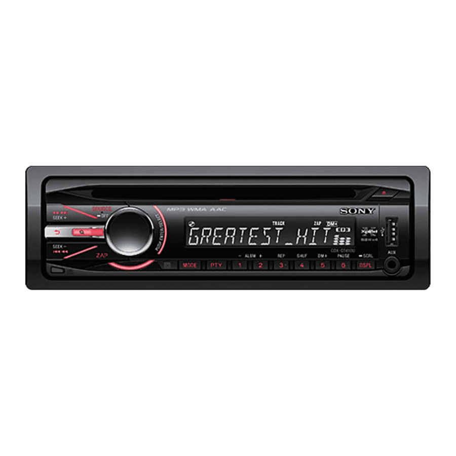
CDX-GT49UM/GT490U/
Photo: CDX-GT490US
Model Name Using Similar Mechanism
CD Drive Mechanism Type
Optical Pick-up Name
SPECIFICATIONS
CD player section
Signal-to-noise ratio: 120 dB
Frequency response: 10 – 20,000 Hz
Wow and fl utter: Below measurable limit
USB Player section
Interface: USB (Full-speed)
Maximum current: 500 mA
Power amplifi er section
Outputs: Speaker outputs (sure seal connectors)
Speaker impedance: 4 – 8 ohms
Maximum power output: 52 W K 4 (at 4 ohms)
General
Outputs:
Audio outputs terminal
(front, sub/rear switchable)
Power antenna (aerial) relay control terminal
Power amplifi er control terminal
Inputs:
Remote controller input terminal
Antenna (aerial) input terminal
AUX input jack (stereo mini jack)
USB signal input terminal
FM/AM COMPACT DISC PLAYER
GT490US/GT494U
CDX-GT490U/GT490US
Indian Model
CDX-GT49UM/GT494U
CDX-GT33U
MG-101Y-188//Q
DAX-25A
Tone controls:
Low: ±10 dB at 60 Hz (XPLOD)
Mid: ±10 dB at 1 kHz (XPLOD)
High: ±10 dB at 10 kHz (XPLOD)
Power requirements: 12 V DC car battery
(negative ground (earth))
Dimensions: Approx. 178 × 50 × 179 mm
1
1
(7
/
× 2 × 7
/
in.) (w/h/d)
8
8
Mounting dimensions:
Approx. 182 × 53 × 162 mm
1
1
1
(7
/
× 2
/
× 6
/
in.) (w/h/d)
4
8
2
Mass: Approx. 1.2 kg (2 lb. 11 oz.)
Supplied accessories:
Card remote commander: RM-X151
Parts for installation and connections (1 set)
Design and specifi cations are subject to change
without notice.
E Model
Advertisement
Table of Contents

Related Manuals for Sony CDX-GT494U


Summarization of Contents
Specifications
Tuner Section Specifications
Tuning ranges, intervals, sensitivity, selectivity, and frequency response for FM/AM.
CD Player Section Specifications
Signal-to-noise ratio, frequency response, and wow/flutter for CD playback.
USB Player Section Specifications
Details on USB interface, speed, and maximum current for USB playback.
Power Amplifier Section Specifications
Output power, speaker impedance, and connector types for the power amplifier.
General Unit Specifications
Details on audio outputs, power requirements, dimensions, and mass.
Tone Controls and Dimensions
Information on tone control ranges and physical dimensions of the unit.
Service Note
Extension Cable and Service Position
Details on connecting extension cables and proper service positioning for repairs.
USB Connector Replacement Notes
Specific guidance for replacing the USB connector, including alignment steps.
Servo Board Replacement Information
Information on replacing the entire servo board due to repair limitations.
20-Pin Connector Handling Precautions
Precautions for cleaning and handling the 20-pin connector to prevent contact issues.
General Information
Connections Overview
Diagrams and explanations for connecting the unit to various components like speakers and power.
Disassembly Procedures
Sub Panel Assembly Disassembly
Step-by-step guide for disassembling the sub-panel assembly.
CD Mechanism Block Disassembly
Instructions for removing the CD mechanism block from the unit.
Main Board Disassembly
Procedures for disassembling and accessing the main circuit board.
Servo Board Disassembly
Steps for removing the servo board from the unit.
Chassis (T) Sub Assembly Disassembly
Detailed guide for disassembling the chassis (T) sub assembly.
Roller Arm Assembly Disassembly
Instructions for disassembling the roller arm assembly.
Chassis (OP) Assembly Disassembly
Steps for disassembling the chassis (OP) assembly.
Chucking Arm Sub Assembly Disassembly
Guide for disassembling the chucking arm sub assembly.
Sled Motor Assembly Disassembly
Procedures for removing the sled motor assembly.
Optical Pick-up Section Disassembly
Steps for disassembling the optical pick-up section.
Optical Pick-up Component Disassembly
Detailed guide for disassembling the optical pick-up component.
Diagrams and Schematics
Block Diagram - Main Section
Overall system block diagram for the main section of the unit.
Block Diagram - Display Section
System block diagram illustrating the display section's functionality.
Printed Wiring Board - Main Section
Layout of the main section's printed wiring board.
Schematic Diagram - Main Section (1/3)
First part of the main section's circuit schematic diagram.
Schematic Diagram - Main Section (2/3)
Second part of the main section's circuit schematic diagram.
Schematic Diagram - Main Section (3/3)
Third part of the main section's circuit schematic diagram.
Printed Wiring Boards - Key Section
Layout of the key section's printed wiring board.
Schematic Diagram - Key Section
Circuit schematic diagram for the key section.
Integrated Circuit (IC) Block Diagrams
Block diagrams illustrating the internal functions of key integrated circuits.
Exploded Views
Main Section Exploded View
Illustrated breakdown of the main section's components and their assembly.
Front Panel Section Exploded View
Illustrated breakdown of the front panel components and their assembly.
CD Mechanism Section Exploded View
Illustrated breakdown of the CD mechanism section's components.
Electrical Parts List
Accessories List
List of supplied accessories, including remote commander and manuals.
Need help?
Do you have a question about the CDX-GT494U and is the answer not in the manual?
Questions and answers