
Related Manuals for eMachines 355 Series


Summary of Contents for eMachines 355 Series
- Page 1 355 Series Service Guide Service guide files and updates are available on the ACER/CSD web; for more information, please refer to http://csd.acer.com.tw PRINTED IN TAIWAN...
- Page 2 Updates Copyright Copyright © 2011 by eMachines Incorporated. All rights reserved. No part of this publication may be reproduced, transmitted, transcribed, stored in a retrieval system, or translated into any language or computer language, in any form or by any means, electronic, mechanical, magnetic, optical, chemical, manual or otherwise, without the prior written permission of eMachines Incorporated.
- Page 3 Conventions The following conventions are used in this manual: Denotes actual messages that SCREEN MESSAGES appear on screen. NOTE Gives bits and pieces of additional information related to the current topic. WARNING Alerts you to any damage that might result from doing or not doing specific actions.
- Page 4 Preface Before using this information and the product it supports, please read the following general information. This Service Guide provides you with all technical information relating to the BASIC CONFIGURATION decided for eMachine's "global" product offering. To better fit local market requirements and enhance product competitiveness, your regional office MAY have decided to extend the functionality of a machine (e.g.
-
Page 5: Table Of Contents
Table of Contents System Specifications ........1 Features . - Page 6 Table of Contents Removing the Button Board ..........73 Removing the LED Board .
- Page 7 355 ........
- Page 8 Table of Contents VIII...
-
Page 9: System Specifications
Chapter 1 System Specifications Features Below is a brief summary of the computer’s many features: Operating System ® Genuine Windows 7 Home Basic 32-bit (China only) ® Genuine Windows 7 Starter CPU and chipset ® Intel Atom™ processor N550/N570 (1 MB L2 cache, 1.50/1.66 GHz, DDR3 667 MHz, 8.5 W) ®... -
Page 10: Storage Subsystem
Storage subsystem Hard disk drive 160/250 GB Multi-in-1 card reader, supporting Secure Digital™ (SD) Card, MultiMediaCard™ (MMC) Storage cards with adapter: miniSD™, microSD™ Webcam Video conferencing solution1, featuring: Webcam with 640 x 480 resolution Microphone Wireless and networking WLAN 802.11b/g/n Wi-Fi CERTIFIED™... -
Page 11: Power Adapter And Battery
24 Wh 2200 mAh 3-cell Li-ion battery pack Battery life: 4 hours Input and control Keyboard 84-/85-/88-key eMachines FineTip keyboard, 93% full-size keyboard, with international language support Touchpad Multi-gesture touchpad, supporting two-finger scroll, pinch, rotate, flip ... - Page 12 Communication and ISP ® Microsoft Silverlight™ Skype™ Windows Live™ Essentials Web links and utilities eMachines Accessory Store (Belgium, France, Germany, Italy, Netherlands, Spain, Sweden, UK only) eMachines Identity Card eMachines Registration eMachines Updater ® eBay shortcut 2009 (Canada, France, Germany, Italy, Mexico, Spain, UK, US only) ...
-
Page 13: System Block Diagram
System Block Diagram DDR2 CRT Conn Memory BUS(DDRII) DDRII-SO-DIMM Pineview FCBGA 559 1.8V DDRII 667 LCD Conn. LVDS GEN1 USB Port X3 Tigerpoint PCI-Express PCBGA360 BlueTooth 17x17mm SATA CMOS CAM MINI Card x1 MINI Card x1 10/100 Ethernet WLAN AR8152L Transfermer WLAN Aralia Codec... -
Page 14: Ddr3
DDR3 CRT Conn Memory BUS(DDRIII) DDRIII-SO-DIMM Pineview FCBGA 559 1.5V DDRIII 667 LCD Conn. LVDS 22x22mm X2 mode GEN1 PCI-Express USB Port x2(L) Tigerpoint PCBGA360 SATA BlueTooth LPC BUS 17x17mm MINI Card x1 10/100 Ethernet CMOS CAM WLAN AR8152 LPC BUS Transfermer USB Port x1(R) Aralia Codec... -
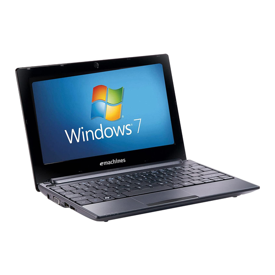
Page 15: Your Notebook Tour
Your Notebook Tour Top View Component Icon Description Microphone Internal microphone for sound recording. Display screen Also called Liquid-Crystal Display (LCD), displays computer output (configuration may vary by model). Power button/ Indicator Turns the computer on and off. Keyboard For entering data into your computer. Touchpad Touch-sensitive pointing device which functions like a computer mouse. -
Page 16: Closed Front View
Closed Front View Component Icon Description Power indicator Light-Emitting Diodes (LED) that light up to show the status of the computer's functions and components. Battery indicator Indicates the computer's battery status. 1. Charging: The light shows amber when the battery is charging. -
Page 17: Right View
Right View Component Icon Description 2-in-one card Accepts Secure Digital (SD), MultiMediaCard (MMC) reader Note: Push to remove/install the card. Only one card can operate at any given time. Headphone/ Connects to line-out audio devices (e.g., speakers, speaker/line-out headphones). jack Microphone-in Accepts inputs from external microphones. -
Page 18: Bottom And Rear View
Bottom and Rear View Component Icon Description Ventilation slots Enables the computer to stay cool, even after prolonged and/or cooling use. Note: Do not cover or obstruct the opening of the fan. Battery release Releases the battery for removal. latch 3G SIM card slot Accepts a 3G SIM card for 3G connectivity (only for certain models). -
Page 19: Touchpad Basics
Touchpad Basics The following items show you how to use the TouchPad: • Move your finger across the TouchPad (1) to move the cursor. • Press the left (2) and right (3) buttons located beneath the TouchPad to perform selection and execution functions. -
Page 20: Using The Keyboard
Using the Keyboard The eMachines 355 has a close-to-full-sized keyboard and an embedded numeric keypad, separate cursor, lock, function and special keys. Lock Keys and Embedded Numeric Keypad The keyboard has three lock keys which you can toggle on and off... -
Page 21: Windows Keys
Windows Keys The keyboard has two keys that perform Windows-specific functions. Description Pressed alone, this key has the same effect as clicking on the Windows Start Windows key button; it launches the Start menu. It can also be used with other keys to provide a variety of functions: <... -
Page 22: Hot Keys
Hot Keys The computer employs hotkeys or key combinations to access most of the computer's controls like screen brightness and volume output. To activate hotkeys, press and hold the <Fn> key before pressing the other key in the hotkey combination. Hotkey Icon Function... - Page 23 Hotkey Icon Function Description Volume down Decreases the sound volume. <Fn> + < > Chapter 1...
-
Page 24: Using The Communication Key
Using the communication key Here you can enable and disable the various wireless connectivity devices on your computer. Press <Fn> + <F3> to bring up the Launch Manager window panel. A red toggle indicates the device is off. Click On to enable wireless/3G/Bluetooth connection. Click Off to disable connection. -
Page 25: Hardware Specifications And Configurations
Hardware Specifications and Configurations Processor Item Specification CPU type Intel® Atom (N455, N475,N550) Processor CPU package Micro-FCBGA8 packaging technologies Core Logic • Intel NM10 Express chipset • Tiger Point(NM10 Express chipset) • On die 512-kB, 8-way L2 cache • On die 2*512-kB, 8-way L2 cache(N550) Chipset •... - Page 26 CPU Fan True Value Table For N45x N47x OS mode CPU Temperature Fan Speed (RPM) SPL Spec (dBA) 4700 5200 5500 5200 5200 5500 Throttling 50%: On=95°C; OFF=80°C OS shut down at100°C; H/W shut down at 90°C For N550 OS mode CPU Temperature Fan Speed (RPM) SPL Spec (dBA)
- Page 27 System Memory (DDR3) Item Specification Memory controller Built in Memory size 1GB/2GB DDR3 RAM (if 2Gb die support is available) DIMM socket number Supports memory size per 2 GB socket Supports maximum memory 2 GB size Supports DIMM type DDR III 667Mhz SDRAM memory interface design Supports DIMM Speed 667Mhz SDRAM Support DIMM voltage...
- Page 28 V1.00 for DDR2 SKU; V3.00 for DDR3 SKU BIOS ROM type Flash BIOS ROM size 2 MB Features • Support ISIPP • Support eMachines UI • Support multi-boot • Suspend to RAM (S3)/Disk (S4) • Various hot-keys for system control • Support SMBUS 2.0, PCI2.3 •...
- Page 29 Keyboard Controller Item Specification Type New eMachines flat keyboard Total number of keypads 84-US/85-UK keys Windows logo key Internal & external keyboard work Plug USB keyboard to the USB port directly: Yes simultaneously Features • 2.0+/- 3mm full stroke keys •...
- Page 30 Hard Disk Drive Interface Item Specification Vendor & Model Western Digital Western Digital Western Digital Name WD1600BEVT- WD2500BEVT- WD3200BEVT- 22A23T0, Hitachi 22A23T0, Hitachi 22A23T0, Hitachi HTS545016B9A300, HTS545025B9A300, HTS545032B9A300, Toshiba MK1665GSX, Toshiba MK2565GSX, Toshiba MK3265GSX, Seagate Seagate ST9250315AS Seagate ST9320315AS ST9160314AS Capacity (GB) 160GB 250GB...
- Page 31 Bluetooth Interface Item Specification Chipset Atheros AR3011/ Broadcom BCM2070/ Broadcom BCM2046 Protocol 3.0+HS Interface USB 2.0 Connector type JST SM08B SURS - TF LED 10.1” Item Specification Vendor/model name AU/ B101AW06 V0/V1CMO/ N101L6-L0D SEC/ LTN101NT05-A01 LG/ LP101WSB-TLN1 & LP101WSB-TLP2 Screen Diagonal (mm) 255.537 (10.1") Active Area (mm) 222.72 (H) X125.28 (V)
- Page 32 LCD Display Supported Resolution Resolution 16 bits 32 bits 640x480p/60Hz 800x600p/60Hz 1024x600p/60Hz 1024x768p/60Hz 1280x720p/60Hz 1280x800p/60Hz 1280x1024p/60Hz 1366x768p/60Hz 1440x900p/60Hz 1600x900p/60Hz 1680x1050p/60Hz 1920x1080p/60Hz Camera Item Specifications Vendor and model Suyin HF1315-S32B- Chicony CNF9157 Lite-on OV01 09P2SF119 Type 1.3M Interface USB Port 2.0 Focusing range >26.6cm Dimensions (L x W x H mm)
- Page 33 Audio Subsystem Item Specification Audio Controller Realtek ALC272X-GR Audio onboard or Built-in optional Mono or Stereo Stereo Resolution 16/20/24 bit stereo full duplex Compatibility HD audio Interface Sampling rate 44.1k/48k/96k/192kHz sample rate Internal microphone Internal speaker/quantity Yes/ 2(1W speaker) USB Port Item Specification USB compliance level...
- Page 34 I/O Ports Item Specification I/O support • VGA port,15 pins • DC-IN • RJ-45 jack for LAN • 3 x USB jacks • Headphone out • Microphone-in • Kensington Lock • 2 in1 card reader AC Adapter Item Specification Input rating Maximum input AC current 1.2A at 100V Inrush current...
- Page 35 System LED Indicator Item Specification Lock System state • Blue color solid on: System on • Blue color off: System off • Orange color blinking: Sleep state HDD access state Blue color: Fast blinking when HDD/SSD/Card reader is running or accessing to data Wireless state Dual color (Blue/Orange) 3G only: Blue...
- Page 36 Chapter 1...
-
Page 37: System Utilities
Chapter 2 System Utilities BIOS Setup Utility The BIOS Setup Utility is a hardware configuration program built into your computer’s BIOS (Basic Input/ Output System). Your computer is already properly configured and optimized, and you do not need to run this utility. However, if you encounter configuration problems, you may need to run Setup. -
Page 38: Information
Information The Information screen displays a summary of your computer hardware information. I n s y d e H 2 0 S e t u p U t i l i t y R e v. 3 . 5 Information Main Security Boot... -
Page 39: Main
Main The Main screen allows the user to set the system time and date as well as enable and disable boot option and recovery. I n s y d e H 2 0 S e t u p U t i l i t y R e v. -
Page 40: Security
Security The Security screen contains parameters that help safeguard and protect your computer from unauthorized use. I n s y d e H 2 0 S e t u p U t i l i t y R e v. 3 . 5 Information Main Security... - Page 41 Setting a Password Follow these steps as you set the user or the supervisor password: Use the and keys to highlight the Set Supervisor Password parameter and press the Enter key. The Set Supervisor Password box appears.: S e t S u p e r v i s o r P a s s w o r d E n t e r N e w P a s s w o r d C o n f i r m N e w P a s s w o r d Type a password in the “Enter New Password”...
- Page 42 Changing a Password Use the and keys to highlight the Set Supervisor Password parameter and press the Enter key. The Set Password box appears. S e t S u p e r v i s o r P a s s w o r d E n t e r C u r r e n t P a s s w o r d E n t e r N e w P a s s w o r d C o n f i r m N e w P a s s w o r d...
- Page 43 If the new password and confirm new password strings do not match, the screen displays the following message. S e t u p W a r n i n g P a s s w o r d s d o n o t m a t c h . R e - e n t e r p a s s w o r d .
-
Page 44: Boot
Boot This menu allows the user to decide the order of boot devices to load the operating system. Bootable devices includes the USB diskette drives, the onboard hard disk drive and the DVD drive in the module bay. I n s y d e H 2 0 S e t u p U t i l i t y R e v. -
Page 45: Exit
Exit The Exit screen allows you to save or discard any changes you made and quit the BIOS Utility. I n s y d e H 2 0 S e t u p U t i l i t y R e v. -
Page 46: Bios Flash Utility
BIOS Flash Utility The BIOS flash memory update is required for the following conditions: New versions of system programs New features or options Restore a BIOS when it becomes corrupted. Use the flash utility to update the system BIOS flash ROM. Note: If you do not have a crisis recovery diskette at hand, then you should create a Crisis Recovery Diskette before you use the flash utility. -
Page 47: Dos Flash Utility
DOS Flash Utility Perform the following steps to use the DOS Flash Utility: Press F2 during boot to enter the Setup Menu. Select Boot Menu to modify the boot priority order, for example, if using USB HDD to Update BIOS, move USB HDD to position 1. - Page 48 In flash BIOS, the message Please do not remove AC Power Source displays. Note: If the AC power is not connected, the following message displays. Warning: No AC power connect Plug in the AC power to continue. Flash is complete when the message Flash programming complete displays. Chapter 2...
-
Page 49: Winflash Utility
WinFlash Utility Perform the following steps to use the WinFlash Utility: Double click the WinFlash executable. Click OK to begin the update. A progress screen displays. InsydeFlash V3.80.00 InsydeFlash Windows(R) BIOS Flash Utility Copyright(C)2009 lnsyde Software Corp http://www.insydesw.com Status Erasing and Writing... New BIOS Current BIOS Version... -
Page 50: Remove Hdd/Bios Password Utilities
Remove HDD/BIOS Password Utilities This section provides you with details about removing HDD/BIOS password methods: Removing HDD Password: If you key in the wrong HDD password three times, an error is generated. To reset the HDD password, perform the following steps: After the error is displayed, select the Enter Unlock Password option on the screen. -
Page 51: Removing Bios Passwords
Removing BIOS Passwords: To clear the User or Supervisor passwords, open the lower door and use a metal instrument to short the CMOS jumper as shown below. Cleaning BIOS Passwords To clean the User or Supervisor passwords, perform the following steps: From a DOS prompt, execute clnpwd.exe Press 1 or 2 to clean the desired password shown on the screen. -
Page 52: Miscellaneous Utilities
Miscellaneous Utilities Using Boot Sequence Selector Boot Sequence Selector allows the boot order to be changes without accessing the BIOS. To use Boot Sequence Selector, perform the following steps: Enter into DOS. Execute BS.exe to display the usage screen. Select the desired boot sequence by entering the corresponding sequence, for example, enter BS2 to change the boot sequence to HDD|CD ROM|LAN|Floppy. - Page 53 Example 1: Read DMI Information from Memory Input: dmitools /r Output: Manufacturer (Type1, Offset04h): eMachines Product Name (Type1, Offset05h): eMachines xxxxx Serial Number (Type1, Offset07h): 01234567890123456789 UUID String (Type1, Offset08h): xxxxxxxx-xxxx-xxxx-xxxx-xxxxxxxxxxxx Asset Tag (Type3, Offset04h): eMachines Asstag Example 2: Write Product Name to EEPROM...
- Page 54 Using the LAN MAC Utility Perform the following steps to write MAC information to eeprom: Use a text editor, for example Notepad, to edit the MAC.CFG file as shown: MAC.CFG - Notepad MAC.CFG - Notepad File Edit Format View Help Title= MAC Address byte WriteData=’001122334455’...
-
Page 55: Creating A Usb Flash Crisis Disk
Creating a USB Flash Crisis Disk Plug in the USB flash disk. Select the Fast Format option and click Start. Then click Next. Click Format and then Exit to complete the operation. Copy the KAV60.fd to the USB flash disk root directory. Note: Do not place any other *.fd files to the USB flash disk root directory. - Page 56 Chapter 2...
-
Page 57: Machine Disassembly And Replacement
Chapter 3 Machine Disassembly and Replacement Important: The outside housing and color may vary from the mass produced model. This chapter contains step-by-step procedures on how to disassemble the notebook computer for maintenance and troubleshooting. Note: These procedures may not reflect the branding of your machine. Disassembly Requirements To disassemble the computer, you need the following tools: ... -
Page 58: General Information
General Information Pre-disassembly Instructions Before proceeding with the disassembly procedure, make sure that you do the following: Turn off the power to the system and all peripherals. Unplug the AC adapter and all power and signal cables from the system. Place the system on a flat, stable surface. -
Page 59: External Module Disassembly Process
External Module Disassembly Process Important: The outside housing and color may vary from the mass produced model. External Modules Disassembly Flowchart The flowchart below gives you a graphic representation on the entire disassembly sequence and instructs you on the components that need to be removed during servicing. For example, if you want to remove the main board, you must first remove the keyboard, then disassemble the inside assembly frame in that order. - Page 60 Screw List Step Screw Quantity Part No. Lower Door M2*7 86.SDE02.005 HDD Module M2*3 86.SDE02.002 HDD Carrier M3*3Ni 86.SDE02.006 3G Module M2*3 86.SDE02.002 WLAN Module M2*3 86.SDE02.002 Chapter 3...
-
Page 61: Removing The Battery Pack
Removing the Battery Pack Turn computer over. Slide the battery lock in the direction shown. Pull and hold the battery release latch into the open position (1), then lift out the battery pack from the main unit (2). Note: The battery has been highlighted with a yellow oval as shown in the above image. Please detach the battery and follow local regulations for disposal. -
Page 62: Removing The Sd Dummy Card
Removing the SD Dummy Card See “Removing the Battery Pack” on page 48. Push the SD dummy card inwards to eject it. Pull the card out from the slot. Chapter 3... -
Page 63: Removing The 3G Card
Removing the 3G Card See “Removing the Battery Pack” on page 48. Push the 3G card into the slot to eject it. Pull the card out from the slot. Chapter 3... -
Page 64: Removing The Keyboard
Removing the Keyboard See “Removing the Battery Pack” on page 48. Push down on the four (4) latches holding the top center of the keyboard. Pull up the top center of the keyboard. Turn the keyboard over. Chapter 3... - Page 65 Unlock the FPC. Remove the FPC and the keyboard. Chapter 3...
-
Page 66: Removing The Lower Door
Removing the Lower Door See “Removing the Keyboard” on page 51. Remove the four (4) screws from the upper cover as shown. Step Size Quantity Screw Type Lower Door M2*7 Using a screwdriver or other straight tool, push through the hole in the upper cover to release the lower door. - Page 67 Turn the computer over and remove the lower cover door. Chapter 3...
-
Page 68: Removing The Dimm Module
Removing the DIMM Module See “Removing the Lower Door” on page 53. Push out the release latches on both sides of the DIMM socket to release the DIMM module. Remove the DIMM module. Chapter 3... -
Page 69: Removing The Hdd Module
Removing the HDD Module See “Removing the Lower Door” on page 53. Remove the one (1) screw from the chassis. Step Size Quantity Screw Type HDD Module M2*3 Grasp the pull-tab and pull the HDD module away from the connector. Chapter 3... - Page 70 Remove the HDD module. Remove the four (4) screws, two on each side, securing the HDD to the carrier. Step Size Quantity Screw Type HDD Carrier M3*3 Ni Chapter 3...
- Page 71 Remove the HDD from the carrier. Chapter 3...
-
Page 72: Removing The 3G Module
Removing the 3G Module See “Removing the Lower Door” on page 53. Disconnect the antenna cables from the 3G module. Note: Cable placement is YELLOW to the MAIN terminal (closest to the edge of the computer) and BLUE to the AUX terminal (closest to the HDD). Move the antennas away and remove the one (1) screw. - Page 73 Remove the 3G module from the 3G socket. Note: When removing the 3G Module, the WLAN antenna cables may be removed to simplify the procedure. Chapter 3...
-
Page 74: Removing The Wlan Module
Removing the WLAN Module See “Removing the Lower Door” on page 53. Disconnect the antenna cables from the WLAN module. Note: Cable placement is Black to the MAIN terminal (closest to the HDD) and White to the AUX terminal (closest to the edge of the computer). Move the antenna cables away and remove the one (1) screw. - Page 75 Note: When removing the WLAN module, the 3G antenna cables may be removed to simplify the procedure. Chapter 3...
-
Page 76: Main Unit Disassembly Process
Main Unit Disassembly Process Main Unit Disassembly Flowchart Screw List Step Screw Quantity Part No. Upper Cover M2*7 86.SDE02.005 Lower Cover M2*5 86.SDE02.004 Button Board M2*3 (t=0.04) 86.SDE02.001 LED Board M2*3) 86.SDE02.002 Speakers M2*3 86.SDE02.002 Mainboard M2*3 86.SDE02.002 Thermal module M2*3 86.SDE02.002 LCD Module... -
Page 77: Removing The Upper Cover
Removing the Upper Cover See “Main Unit Disassembly Flowchart” on page 60. Unlock and remove the touchpad FFC. Unlock and remove the LED FFC. Chapter 3... - Page 78 Remove the four (4) remaining screws from the upper cover. Step Size Quantity Screw Type Upper Cover M2*7 Remove the seven (7) screws from the chassis. Step Size Quantity Screw Type Lower Cover M2*5 Chapter 3...
- Page 79 Starting at the top left corner, pull up on the upper cover to unhook the latches which secure the top cover to the chassis. Continue by inserting a flat, plastic tool to unhook the remaining latches as shown. Note: To prevent damage to the internal components, do not push the tool in too far. Chapter 3...
- Page 80 Use a plastic tool to unlock the two latches (red callouts) located above the HDD cover. Remove the upper cover. Chapter 3...
-
Page 81: Removing The Button Board
Removing the Button Board See “Removing the Upper Cover” on page 61. Locate the button board on the upper cover. Release the touchpad FFC locking latch and disconnect the touchpad FFC from the cover. Pull the button board FFC off the adhesive. Chapter 3... - Page 82 Remove the two (2) screws securing the button board to the upper cover. Step Size Quantity Screw Type Button Board M2*3 (t=0.04) Remove the button board from the upper cover. Chapter 3...
-
Page 83: Removing The Led Board
Removing the LED Board See “Removing the Upper Cover” on page 61. Remove the one (1) screw from the chassis. Step Size Quantity Screw Type LED Board M2*3 Remove the LED board from the chassis. Chapter 3... -
Page 84: Removing The Bluetooth Module
Removing the Bluetooth Module See “Removing the Upper Cover” on page 61. 2. Remove the adhesive tape securing the Bluetooth cable to the chassis. Disconnect the Bluetooth cable from the mainboard connector. Lift the Bluetooth module off the adhesive. Chapter 3... - Page 85 Disconnect the cable from the Bluetooth module. Chapter 3...
-
Page 86: Removing The Rtc Battery
Removing the RTC Battery See “Removing the Upper Cover” on page 61. The RTC battery is soldered in place. Break the solder and remove the RTC battery. Note: The battery has been highlighted with a yellow oval as shown in the above image. Please detach the battery and follow local regulations for disposal. -
Page 87: Removing The Speaker Module
Removing the Speaker Module See “Removing the Upper Cover” on page 61. Remove the adhesive tape securing the speaker cable. Disconnect the speaker cable from the mainboard connector. Remove the speaker cable from the cable guides. Chapter 3... - Page 88 Remove the four (4) screws from the chassis. Step Size Quantity Screw Type Speakers M2*3 Remove the speakers from the chassis. Chapter 3...
-
Page 89: Removing The Mainboard
Removing the Mainboard Note: Ensure speaker cable is clear before removal of mainboard. See “Removing the LED Board” on page 67. Pull the LVDS grounding wire from the 3G card casing. Disconnect the LVDS cable from the connector. Chapter 3... - Page 90 Remove the LVDS cable from the adhesive strip on the mainboard. Disconnect the DC-In cable from the connector. Pull the microphone grounding wire from the LAN casing. Chapter 3...
- Page 91 Disconnect the microphone cable from the connector. Remove the adhesive tape securing the speaker cable. Disconnect the speaker cable from the mainboard connector. Chapter 3...
- Page 92 10. Remove the two (2) screws from the chassis. Step Size Quantity Screw Type Mainboard M2*3 11. With one hand, pull up on the bridge of the mainboard (1) and with the other, hold the bottom of chassis and press up and out (2). Chapter 3...
- Page 93 12. Remove the mainboard from the chassis. Chapter 3...
-
Page 94: Removing The Thermal Module
Removing the Thermal Module See “Removing the Mainboard” on page 72. Disconnect the fan cable from the connector. Remove the three (3) screws in order from 1 to 3. Step Size Quantity Screw Type Thermal module M2*3 Chapter 3... - Page 95 Remove the thermal module from the mainboard. Note: Circuit boards >10 cm² have been highlighted with a yellow rectangle as shown in the previous image. Please detach the Circuit board and follow local regulations for disposal. Chapter 3...
-
Page 96: Removing The Lcd Module
Removing the LCD Module See “Removing the Mainboard” on page 72. Remove the DC-In cable and jack housing from the chassis. Remove the left antenna cables from the cable guides on the bottom cover. Lift up the chassis and pull the left antenna cables through to the front. Chapter 3... - Page 97 Remove the left antenna cables from the retention guides. Pull the right antenna cables through the chassis and remove the cables from the retention guides. Chapter 3...
- Page 98 Remove the two (2) hinge screws from the chassis. Step Size Quantity Screw Type LCD Module M2*4 Ni Remove the LCD module from the chassis. Chapter 3...
-
Page 99: Lcd Module Disassembly Process
LCD Module Disassembly Process LCD Module Disassembly Flowchart Screw List Step Screw Quantity Part No. LCD Bezel M2*4 Ni 86.SDE02.003 LCD Panel M2*3(t=0.04) 86.SDE02.001 LCD Panel M2*3(t=0.04) 86.SDE02.001 Brackets Chapter 3... -
Page 100: Removing The Lcd Bezel
Removing the LCD Bezel See “Removing the LCD Module” on page 78. Remove the two (2) screw caps and two (2) screws from the module. Step Size Quantity Screw Type LCD Bezel M2*4 Ni Chapter 3... - Page 101 Starting from the bottom-center of the bezel, pry the bezel upwards and away from the panel. Move along the edge until the bezel is completely removed. Chapter 3...
-
Page 102: Removing The Camera Module
Removing the Camera Module See “Removing the LCD Bezel” on page 82. Disconnect the camera cable from the connector. Pull the camera away from the adhesive strip and lift it out of the LCD module. Chapter 3... -
Page 103: Removing The Lcd Panel
Removing the LCD Panel Caution: The LCD module displayed here may be different from model purchased. See “Removing the Camera Module” on page 83. Remove the four (4) securing screws from the LCD Panel. Step Size Quantity Screw Type LCD Panel M2*3 Lift up the adhesive foil covering the LVDS cable. - Page 104 Lift the LCD Panel out of the module. Turn the LCD panel over and place it face down on a clean surface. Remove the adhesive tape securing the camera cable to the panel Chapter 3...
- Page 105 Remove the camera cable from the back of the LCD panel. Peel up the transparent adhesive protector securing the LVDS cable to the LCD Panel. Disconnect the LVDS cable from the panel connector and lift the panel away. Chapter 3...
-
Page 106: Removing The Microphone Module
Removing the Microphone Module See “Removing the LCD Panel” on page 84. Lift up the adhesive tape and foil tab covering the microphone cable. Remove the adhesive tape covering the microphone and lift it clear of the LCD module. Chapter 3... -
Page 107: Removing The Lcd Brackets
Removing the LCD Brackets See “Removing the LCD Panel” on page 84. Remove the four (4) screws from the LCD brackets. Step Size Quantity Screw Type LCD Panel M2*3 (t=0.04) Brackets Lift the brackets away from the upper cover. Chapter 3... -
Page 108: Removing The 3G And Wlan Antennas
Removing the 3G and WLAN Antennas See “Removing the LCD Brackets” on page 88. Lift the adhesive foam padding off the adhesive foil. Lift the adhesive foam padding off the left 3G antenna. Lift the left antenna foil off the LCD cover. Chapter 3... - Page 109 Remove the left 3G antenna. Remove the cable from the retention guides Pry the left WLAN antenna off the LCD module cover and remove. Repeat steps 2 - 7 for the right 3G and WLAN antennas. Chapter 3...
-
Page 110: Lcd Module Reassembly Procedure
LCD Module Reassembly Procedure Replacing the 3G and WLAN Antennas Place the left WLAN antenna onto the LCD module cover and apply pressure to adhere it to the LCD cover. Place the left 3G antenna onto the LCD cover as shown. Chapter 3... - Page 111 Apply pressure to the left antenna foil to set the adhesive. Replace the adhesive foam padding onto the left 3G adhesive foil and apply pressure to fix the adhesive. Place the left antenna cables into the retention guides and replace the adhesive foil tabs to secure the cables.
- Page 112 Replace the adhesive foam on the top of the left 3G antenna and apply pressure to fix the adhesive. Repeat steps 1 to 6 for the right antenna cables. Chapter 3...
-
Page 113: Replacing The Lcd Brackets
Replacing the LCD Brackets Place the brackets onto the upper cover. Replace the four (4) screws to secure the LCD brackets. Step Size Quantity Screw Type LCD Panel M2*3(t=0.04) Brackets Chapter 3... -
Page 114: Replacing Microphone Module
Replacing Microphone Module Adhere the microphone to the LCD cover. Place the microphone cable along the bottom of the LCD cover and replace the foil tabs over the microphone cable. Lay the camera cable across the LCD cover as shown. Chapter 3... - Page 115 Replace the adhesive tape and foil tabs to secure the cable. Chapter 3...
-
Page 116: Replacing The Lvds Cable
Replacing the LVDS Cable Replace the LCD cable connector. Adhere the transparent connector protector. Place the LCD panel onto the LCD cover and replace the adhesive foil tabs to secure the LVDS cable. Chapter 3... - Page 117 Replace the four (4) screws to secure the LCD Panel. Step Size Quantity Screw Type LCD Panel M2*3(t=0.04) Chapter 3...
-
Page 118: Replacing The Ccd Module
Replacing the CCD Module Adhere the CCD to the LCD module cover. Connect the CCD cable to the CCD module connector. Chapter 3... -
Page 119: Replacing The Lcd Bezel
Replacing the LCD Bezel Locate the bezel hinges first and press down until there are no gaps between the bezel and the LCD module cover hinge wells. Note: Ensure that the LCD cables pass through the hinge wells and are not trapped by the bezel. Press down around the entire perimeter of the bezel until there are no gaps between the bezel and the LCD module. - Page 120 Secure the two (2) screws and screw covers to secure the LCD bezel. Step Size Quantity Screw Type LCD Bezel M2*4 Ni Chapter 3...
-
Page 121: Main Module Reassembly Procedure
Main Module Reassembly Procedure Replacing the LCD Module Place the LCD module onto the main unit lower cover. Secure the two (2) screws to the chassis. Step Size Quantity Screw Type LCD Module M2*4 Chapter 3... - Page 122 Place the right antenna cables under the retention guides and pull the antenna cables through the chassis as shown. Place the left antenna cables into the retention guides as shown. Lift up the chassis and pull the left antenna cables through to the back. Chapter 3...
- Page 123 Place the left antenna cables into the cable guides on the bottom cover. Replace the DC-In power jack. Chapter 3...
-
Page 124: Replacing The Thermal Module
Replacing the Thermal Module Important: Apply a suitable thermal grease and ensure all heat pads are in place before replacing the thermal module. The following thermal grease types are approved for use: Silmore GP50 Honeywell PCM45F-SP ShinEtsu 7762 ... - Page 125 Secure the three (3) screws in reverse sequential order from 3 to 1. Step Size Quantity Screw Type Thermal Module M2*3(t=0.04) Connect the thermal module cable to the mainboard connector. Chapter 3...
-
Page 126: Replacing The Mainboard
Replacing the Mainboard Place the mainboard into the chassis as shown. While lifting up at the mainboard bridge (1), apply gentle pressure to the connector end to fit the mainboard into the chassis (2). Chapter 3... - Page 127 Replace the two (2) screws to secure the mainboard. Step Size Quantity Screw Type Mainboard M2*3 Connect the speaker cable to the connector. Chapter 3...
- Page 128 Replace the adhesive tape to secure the speaker cable. Connect the microphone cable to the mainboard connector. Adhere the microphone grounding wire to the LAN casing. Chapter 3...
- Page 129 Connect the DC-In power cable. 9. Adhere the LVDS cable to the adhesive strip on the mainboard. 10. Connect the LVDS cable to the main board connector. Chapter 3...
- Page 130 11. Adhere the LVDS grounding wire to the 3G card casing. Chapter 3...
-
Page 131: Replacing The Speakers
Replacing the Speakers Place the two speaker housings onto the chassis. Secure the four (4) screws and place the cables into the retention guides. Step Size Quantity Screw Type Speakers M2*3 Chapter 3... -
Page 132: Replacing The Rtc Battery
Replacing the RTC Battery Place the RTC battery onto the mainboard plus (+) side down and solder the connections to secure it in place. Chapter 3... -
Page 133: Replacing The Bluetooth Module
Replacing the Bluetooth Module Connect the Bluetooth cable to the Bluetooth module Adhere the Bluetooth module to the chassis. Connect the Bluetooth cable to the mainboard connector. Chapter 3... -
Page 134: Replacing The Led Board
Replacing the LED Board Place the LED board onto the chassis. Secure the LED board to the chassis using one (1) screw. Step Size Quantity Screw Type LED Board M2*3 Chapter 3... -
Page 135: Replacing The Button Board
Replacing the Button Board Place the button board onto the upper cover. Secure the button board to the upper cover using two (2) screws. Step Size Quantity Screw Type Button Board M2*3 (t=0.04) Chapter 3... - Page 136 Adhere the button board FFC to the upper cover. Connect and lock the touchpad FFC to the connector. Chapter 3...
-
Page 137: Replacing The Upper Cover
Replacing the Upper Cover Place the upper cover onto the chassis ensuring the hinge covers are seated properly. Press down around the upper cover edges to secure the latches. Press down on the center of the upper cover to secure the center latches. Chapter 3... - Page 138 Secure the upper cover to the chassis using seven (7) screws. Step Size Quantity Screw Type Lower Cover M2*5 Secure the upper cover to the chassis using four (4) screws. Step Size Quantity Screw Type Upper Cover M2*7 Chapter 3...
- Page 139 Connect and lock the LED FFC to the connector. 6. Connect and lock the touchpad FFC to the connector. Chapter 3...
-
Page 140: Replacing The Wlan Module
Replacing the WLAN Module Push the WLAN module into the connector. Secure the WLAN module to the chassis using one (1) screw. Step Size Quantity Screw Type WLAN Module M2*3 Chapter 3... - Page 141 Secure the two (2) antennas to the connectors. Note: Cable placement is Black to the MAIN terminal (closest to the HDD) and White to the AUX terminal (closest to the edge of the computer). Chapter 3...
-
Page 142: Replacing The 3G Module
Replacing the 3G Module Push the 3G module into the connector. Secure the 3G module to the chassis using one (1) screw. Step Size Quantity Screw Type 3G Module M2*3 Chapter 3... - Page 143 Secure the two (2) antennas to the connectors. Note: Cable placement is YELLOW to the MAIN terminal (closest to the edge of the computer) and BLUE to the AUX terminal (closest to the HDD). Chapter 3...
-
Page 144: Replacing The Hdd Module
Replacing the HDD Module Place the HDD into the carrier. Secure the four (4) screws, two (2) on each side, to secure the HDD carrier. Step Size Quantity Screw Type HDD Module M3*3 Ni Chapter 3... - Page 145 Place the HDD module into the HDD bay. Push the HDD module forward to engage the connector. Chapter 3...
- Page 146 Secure the HDD module to the chassis using one (1) screw. Step Size Quantity Screw Type HDD Module M2*3 Chapter 3...
-
Page 147: Replacing The Dimm Module
Replacing the DIMM Module Push the DIMM module into the connector. Press down to lock the DIMM module into place. Chapter 3... -
Page 148: Replacing The Lower Cover
Replacing the Lower Cover Place the back edge of the lower cover door against the chassis (1) and then lower the front edge into place (2). Apply gentle pressure to secure the latches. Secure the lower cover to the chassis using four (4) screws. Step Size Quantity... -
Page 149: Replacing The Keyboard
Replacing the Keyboard Connect the keyboard FPC and lock the connector. Turn the keyboard over ensuring the latches are inserted into the connectors at the bottom of the keyboard bay. Apply gentle pressure to secure the keyboard latches. Chapter 3... -
Page 150: Replacing The 3G Card
Replacing the 3G Card Push the 3G card into the slot until it clicks into place. Chapter 3... -
Page 151: Replacing The Sd Dummy Card
Replacing the SD Dummy Card Insert the SD dummy card into the slot. Push the card in until it clicks into place and is flush with the casing Chapter 3... -
Page 152: Replacing The Battery
Replacing the Battery Pull the battery release latch into the open position then (1) insert the battery pack and push into place (2). Push the battery lock latch in the direction shown to secure the battery. Chapter 3... -
Page 153: Troubleshooting
Chapter 4 Troubleshooting Common Problems Use the following procedure as a guide for computer problems. NOTE: The diagnostic tests are intended to test only Acer products. Non-Acer products, prototype cards, or modified options can give false errors and invalid system responses. Obtain the failing symptoms in as much detail as possible. -
Page 154: Power On Issue
Power On Issue If the system doesn’t power on, perform the following actions one at a time to correct the problem. Do not replace a non-defective FRUs: Start Swap AC/Battery Check AC/Batt only power on Check Swap Power Power/B SW/B Whether OK Swap M/B Computer Shutsdown Intermittently... -
Page 155: No Display Issue
No Display Issue If the Display doesn’t work, perform the following actions one at a time to correct the problem. Do not replace a non-defective FRU. START Replace LCD LCD panel/cable ok? go to no power panel/cable Power On? trouble shooting step Replace Ext. -
Page 156: Random Loss Of Bios Settings
Abnormal Video Display If video displays abnormally, perform the following actions one at a time to correct the problem. Reboot the computer. If permanent vertical/horizontal lines or dark spots display in the same location, the LCD is faulty and should be replaced. See “LCD Module Disassembly Process” on page 91. If extensive pixel damage is present (different colored spots in the same locations on the screen), the LCD is faulty and should be replaced. -
Page 157: Lcd Failure
LCD Failure If the LCD fails, perform the following actions one at a time to correct the problem. Do not replace a non- defective FRU. Start Swap LCD cable Check LCD /LCD panel module? Swap M/B Chapter 4... -
Page 158: Built-In Keyboard Failure
Built-In Keyboard Failure If the built-in Keyboard fails, perform the following actions one at a time to correct the problem. Do not replace a non-defective FRU. START Keyboard FPC Connect well connected? it well Replace Keyboard OK? keyboard Replace M/B Chapter 4... -
Page 159: Touchpad Failure
TouchPad Failure If the TouchPad doesn’t work, perform the following actions one at a time to correct the problem. Do not replace a non-defective FRU. Start Re-assemble the T/P FFC to Check M/B T/P FFC Swap/Re- Check Logic assemble the Upper T/P board or T/P FFC... - Page 160 Sound Problems If sound problems are experienced, perform the following actions one at a time to correct the problem. Reboot the computer. Navigate to Start Control Panel System and Maintenance System Device Manager. Check the Device Manager to determine that: The device is properly installed.
-
Page 161: Internal Microphone Failure
Internal Microphone Failure If the internal Microphone fails, perform the following actions one at a time to correct the problem. Do not replace a non-defective FRU. Start Check M/B Mic. Re-assemble the cable MIC cable to M/B Swap M/B Microphone Problems If internal or external Microphones do no operate correctly, perform the following actions one at a time to correct the problem. -
Page 162: Hdd Not Operating Correctly
HDD Not Operating Correctly If the HDD does not operate correctly, perform the following actions one at a time to correct the problem. Disconnect all external devices. Run a complete virus scan using up-to-date software to ensure the computer is virus free. Run the Windows 7 Startup Repair Utility: insert the Windows 7 Operating System DVD in the ODD and restart the computer. -
Page 163: Usb Failure
USB Failure If the USB fails, perform the following actions one at a time to correct the problem. Do not replace a non- defective FRU. Start Check USB/B to Re-assemble the USB/B cable to M/B M/B cable Swap USB/B and Check USB/B USB cable Swap M/B... -
Page 164: Wireless Function Failure
Wireless Function Failure If the WLAN fails, perform the following actions one at a time to correct the problem. Do not replace a non- defective FRU. Start Re-assemble Check WL the antenna to antenna to WL WL card card Swap The Check antenna antenna... -
Page 165: 3G Function Failure
3G Function Failure If the 3G module fails, perform the following actions one at a time to correct the problem. Do not replace a non-defective FRU. Start Re-assemble Check 3G the antenna to antenna to 3G card 3G card Swap The Check antenna antenna... -
Page 166: Cosmetic Failure
Cosmetic Failure If an external component fails, perform the following actions one at a time to correct the problem. Do not replace a non-defective FRU. Start LCD cover? Swap LCD cover Swap LCD LCD bezel? bezel Swap Upper Upper? Swap Lower Lower? Function Test Chapter 4... -
Page 167: Thermal Unit Failure
Thermal Unit Failure If the Thermal Unit fails, perform the following actions one at a time to correct the problem. Do not replace a non-defective FRU. START Fan power cable well Connect it well connected? Fan OK? Replace fan Heat sink well Seat it well seated? Replace M/B... -
Page 168: External Mouse Failure
External Mouse Failure If an external Mouse fails, perform the following actions one at a time to correct the problem. Try an alternative mouse. If the mouse uses a wireless connection, insert new batteries and confirm there is a good connection. See the mouse user manual. -
Page 169: Intermittent Problems
Intermittent Problems Intermittent system hang problems can be caused by a variety of reasons that have nothing to do with a hardware defect, such as: cosmic radiation, electrostatic discharge, or software errors. FRU replacement should be considered only when a recurring problem exists. When analyzing an intermittent problem, do the following: Run the advanced diagnostic test for the system board in loop mode at least 10 times. -
Page 170: Post Codes
Post Codes These tables describe the POST codes and descriptions during the POST. Sec: NO_EVICTION_MODE_DEBUG EQU 1 (CommonPlatform\sec\Ia32\SecCore.inc) Code Description 0xC2 MTRR setup 0xC3 Enable cache 0xC4 Establish cache tags 0xC5 Enter NEM, Place the BSP in No Fill mode, set CR0.CD = 1, CR0.NW = 0. 0xCF Cache Init Finished Memory:... -
Page 171: Bds & Specific Action
Code Description 0x28 Enable all clocks on populated rows 0x29 Perform JEDEC memory initialization for all memory rows 0x30 Perform steps required after memory init 0x31 Program DRAM throttling and throttling event registers 0x32 Setup DRAM control register for normal operation and enable 0x33 Enable RCOMP 0x34... -
Page 172: Each Peim Entry Point Used In 80_Port
Each PEIM entry point used in 80_PORT Code Description 0x00 0x01 PEI_EVENT_LOG 0xA1 PEI_OEM_SERVICE 0xA2 PEI_SIO_INIT 0xA3 PEI_MONO_STATUS_CODE 0xA4 PEI_CPU_IO_PCI_CFG 0x06 PEI_CPU_IO 0x07 PEI_PCI_CFG 0xA5 PEI_CPU_PEIM 0xA6 PEI_PLATFORM_STAGE1 0xA7 PEI_VARIABLE 0xA8 PEI_SB_INIT 0x0C PEI_CAPSULE 0xAA PEI_PLATFORM_STAGE2 0xAC PEI_SB_SMBUS_ARP_DISABLED 0x0F PEI_HOST_TO_SYSTEM 0x40 PEI_MEMORY_INIT 0x41... - Page 173 Code Description 0xC4 SECURITY_STUB 0xC5 DXE_CPU_IO 0xC6 CF9_RESET 0xC7 PC_RTC 0xC8 STATUS_CODE 0xC9 VARIABLE EMU_VARIABLE 0xD9 DXE_CHIPSET_INIT 0x45 DXE_ALERT_FORMAT 0xD6 PCI_HOST_BRIDGE 0xD7 PCI_EXPRESS 0xD5 DXE_SB_INIT 0xDA IDE_CONTROLLER 0xDB SATA_CONTROLLER 0xDD SB_SM_BUS 0xE7 ISA_ACPI_DRIVER 0xE8 ISA_BUS 0xE9 ISA_SERIAL 0xED BUS_PCI_UNDI 0xEC PCI_BUS 0xF6 BOOT_PRIORITY...
- Page 174 Code Description 0x72 MONITER_KEY 0x73 LEGACY_BIOS 0x75 LEGACY_BIOS_PLATFORM 0x76 PCI_PLATFORM 0x6C ISA_FLOOPY 0x6D PS2_MOUSE 0x6E USB_BOT 0x6F USB_CBI0 0x74 USB_MOUSE 0xFA SETUP_UTILITY 0x90 FW_BLOCK_SERVICE 0x78 SMM_USB_LEGACY 0x86 GRAPHICS_CONSOLE 0x87 TERMINAL 0x8A DATA_HUB_STD_ERR 0x7C 0x7D PARTITION 0x7E ENGLISH 0x7F FRENCH 0x9E HII_DATABASE 0x9F OEM_SETUP_BROWSER...
-
Page 175: Each Smmdriver Entry Point Used In 80_Port
Each SmmDriver entry point used in 80_PORT Code Description 0xD4 SMM_ACCESS 0xDE SMM_CONTROL 0xCC SMM_BASE 0xD2 SMM_RUNTIME 0xDF SB_SMM_DISPATCH 0xD0 SMM_THUNK 0xCA SMM_ACPI_SW_CHILD 0xFE SMM_PLATFORM 0xD8 SMM_GMCH_MBI 0x90 SMM_FW_BLOCK_SERVICE 0x91 SMM_VARIABLE 0x92 SMM_IHISI 0x93 SMM_INT15_MICROCODE 0x94 SMM_PNP 0x95 SMM_INIT_PPM 0xD3 SMM_OEM_SERVICE Chapter 4... - Page 176 Chapter 4...
-
Page 177: Jumper And Connector Locations
Chapter 5 Jumper and Connector Locations Mainboard Top View Item Description JRJ45 RJ45 CONNECTOR JP26 MICROPHONE CONNECTOR JUSB3 USB CONNECTOR JMIC 1 AUDIO JACK (MIC) JHP 1 AUDIO JACK (HEAD PHONE) JP20 SPEAKER CONNECTOR JBT 1 BLUETOOTH CONNECTOR JPI 1 TOUCH PAD CONNECTOR JKB 1 KEYBOARD CONNECTOR... -
Page 178: Mainboard Bottom View
Mainboard Bottom View Item Description JDIMI DDR2 CONNECTOR JMINI 1 MINI CARD CONNECTOR JMINI 2 MINI CARD CONNECTOR JPI2 FAN CONNECTOR JHDD1 HDD CONNECTOR PJP2 BATTERY CONNECTOR Chapter 5... -
Page 179: Clearing Password Check And Bios Recovery
Clearing Password Check and BIOS Recovery This section provide you the standard operating procedures of clearing password and BIOS recovery for the computer. There is one Hardware Open Gap on the mainboard for clearing password check, and one Hotkey for enabling BIOS Recovery. Clearing Password Check Hardware Open Gap Description is as follows: Item... -
Page 180: Bios Recovery By Crisis Disk
BIOS Recovery by Crisis Disk BIOS Recovery Boot Block: BIOS Recovery Boot Block is a special block of BIOS. It is used to boot up the system with minimum BIOS initialization. Users can enable this feature to restore the BIOS firmware to a successful one once the previous BIOS flashing process failed. - Page 181 Chapter 5...
- Page 182 Chapter 5...
-
Page 183: Fru (Field Replaceable Unit) List
Chapter 6 FRU (Field Replaceable Unit) List This chapter gives you the FRU (Field Replaceable Unit) listing in global configurations of the computer. Refer to this chapter whenever ordering for parts to repair or for RMA (Return Merchandise Authorization). Please note that WHEN ORDERING FRU PARTS, you should check the most up-to-date information available on your regional web or channel. -
Page 184: Main Assembly
Exploded Diagrams Main Assembly Description Acer P/N Description Acer P/N UPPER CASE 60.NE502.001 LED BOARD 55.SDE02.002 FOR W/O 3G MAINBOARD MB.SDF02.001 LOWER CASE 60.SDE02.002 THERMAL MODULE W/FAN 60.SDE02.006 LOGIC DOOR 60.NE502.002 DC IN CABLE 50.SDE02.003 Chapter 6... -
Page 185: Logic Lower Assembly
Logic Lower Assembly Description Acer P/N Description Acer P/N SPEAKER R+L 23.SDE02.002 LOWER CASE 60.SDE02.002 Chapter 6... -
Page 186: Logic Upper Assembly
Logic Upper Assembly Description Acer P/N Description Acer P/N BUTTON BOARD 55.SDE02.001 UPPER CASE 60.NE502.001 Chapter 6... -
Page 187: Lcd Assembly
LCD Assembly Description Acer P/N Description Acer P/N LCD BEZEL 60.NE502.004 LCD BRACKET R&L 33.SDE02.002 ANTENNA 3G AUX LCD COVER IMR- 60.NE502.003 BLACK W/O 3G ANTENNA WLAN AUX 50.SDE02.005 ANTENNA WLAN MAIN 50.SDE02.004 LCD CABLE FOR W/O 50.SDE02.008 ANTENNA 3G MAIN CAMERA 1.3M 57.SDE02.001 Chapter 6... -
Page 188: Fru List
FRU List CATEGORY Description ADAPTER Adapter DELTA 40W 19V 1.7x5.5x11 Black ADP-40 TH AA, AP.04001.002 LV5 wall-mounted, OBL LF Adapter LEADER 40W 19V 1.7x5.5x11 Black IU40-11190- AP.04007.002 011S, wall-mounted, LV5+OBL LF BATTERY Battery SANYO AL10A Li-Ion 3S1P SANYO 3 cell 2200mAh BT.00303.022 Main COMMON ID:AL10A31 Battery SANYO AL10B Li-Ion 3S2P SANYO 6 cell 4400mAh... - Page 189 CATEGORY Description AC CLIP US 27.WH202.001 AC CLIP EU 27.WH202.002 AC CLIP AUSTRALIA 27.WH202.003 AC CLIP UK 27.WH202.004 AC CLIP ARGETINA 27.WH202.005 AC CLIP CHINA 27.WH202.006 AC CLIP BRAZIL 27.WH202.007 AC CLIP S-AFRICA 27.WH202.008 AC CLIP KOREA 27.WH202.009 AC CLIP AF 27.WH202.010 ANTENNA WLAN MAIN 50.SDE02.004...
- Page 190 CATEGORY Description HDD/HARD DISK DRIVE HDD HGST 2.5" 5400RPM 160GB HTS545016B9A300 KH.16007.026 PANTHER B SATA LF F/W:C60F DISK IMBALANCE CRITERIA = 0.014G-CM HDD TOSHIBA 2.5" 5400RPM 160GB MK1665GSX, KH.16004.008 CAPRICORN BS, 320G/P SATA 8MB LF F/W:GJ002J HDD WD 2.5" 5400RPM 160GB WD1600BEVT-22A23T0 , WD, KH.16008.027 ML320S SATA 8MB LF F/W:01.01A01 HDD SAMSUNG 2.5"...
- Page 191 CATEGORY Description KEYBOARD Keyboard ACER NT0T_A10B NT0T Internal 10 Standard 84KS KB.I100A.086 Black US International Texture Keyboard ACER NT0T_A10B NT0T Internal 10 Standard 84KS KB.I100A.070 Black Greek Texture Keyboard ACER NT0T_A10B NT0T Internal 10 Standard 84KS KB.I100A.061 Black Arabic Texture Keyboard ACER NT0T_A10B NT0T Internal 10 Standard 84KS KB.I100A.065 Black Chinese Texture...
- Page 192 CATEGORY Description Keyboard ACER NT0T_A10B NT0T Internal 10 Standard 85KS KB.I100A.079 Black SLO/CRO Texture Keyboard ACER NT0T_A10B NT0T Internal 10 Standard 85KS KB.I100A.064 Black CZ/SK Texture Keyboard ACER NT0T_A10B NT0T Internal 10 Standard 85KS KB.I100A.063 Black Brazilian Portuguese Texture Keyboard ACER NT0T_A10B NT0T Internal 10 Standard 88KS KB.I100A.073 Black Japanese Texture ASSY LED MODULE 10.1"...
- Page 193 CATEGORY Description MAINBOARD MAINBOARD AOD255 INTEL NM10 LF N450 W/O 3G MB.SDF02.001 MAINBOARD AOD255 INTEL NM10 LF N455 CPU W/O 3G MB.SDH02.002 MAINBOARD AOD255 INTEL NM10 LF N475CPU, W/O 3G, MB.SDJ02.001 W/O MCP MAINBOARD AOD255 INTEL NM10 LF N550 W/O 3G MB.SDH02.001 Mainboard AOD255E Intel NM10 LF N570 CPU, w/o 3G MB.SEW02.001...
- Page 194 CATEGORY Description SPEAKER MIC SET 23.SDE02.001 SPEAKER R+L 23.SDE02.002 Chapter 6...
-
Page 195: Screw List
Screw List CATEGORY Description SCREW SCREW 2D 3L K 4.5D ZK NL CR3 0.4T 86.SDE02.001 SCREW 2D 3L K 4.5D ZK NL 86.SDE02.002 SCREW 2D 4.0L K 4.0D NI NL 0.3T 86.SDE02.003 SCREW 2D 5L K 4.6D ZK NL CR3 86.SDE02.004 SCREW 2D 7L K 4.6D ZK NL CR3 86.SDE02.005... - Page 196 Chapter 6...
-
Page 197: Model Definition And Configuration
Appendix A Model Definition and Configuration eMachines 355 Model Country Description eM355-131G16ikk LU.NE50C.001 CHINA eM355-131G16ikk LinpusMGeCN1 UMACkk_3 1*1G/160/3L2.2/2R/ CBSDS_GN_0.3C_GEk_ZH41 eM355-131G16ikk LU.NE50D.011 EMEA eM355-131G16ikk SNW7ST32eSDE1 UMACkk_3 1*1G/160/6L2.2/2R/ CBSDS_GN_0.3C_GEk_DE11 eM355-131G16ikk MOYO LU.NE50D.063 EMEA eM355-131G16ikk EM SNW7ST32EMeSME1 UMACkk_3 1*1G/160/BT/3L2.2/2R/ CBSDS_GN_0.3C_GEk_ARA1 eM355-131G16ikk LU.NE50D.006 EMEA eM355-131G16ikk SNW7ST32RUeSRU1 UMACkk_3 1*1G/160/3L2.2/2R/... - Page 198 Model Country Description eM355-131G25ikk Czech LU.NE50D.039 EMEA eM355-131G25ikk SNW7ST32eSCZ2 UMACkk_3 1*1G/250/3L2.2/2R/ NASD_GN_0.3C_GEk_SK11 eM355-131G25ikk LU.NE50D.012 EMEA eM355-131G25ikk SNW7ST32eSDE1 UMACkk_3 1*1G/250/6L2.2/2R/ NASD_GN_0.3C_GEk_DE11 eM355-131G25ikk LU.NE50D.044 EMEA eM355-131G25ikk SNW7ST32eSDE1 UMACkk_3 1*1G/250/3L2.2/2R/ NASD_GN_0.3C_GEk_DE11 eM355-131G25ikk LU.NE50D.040 EMEA eM355-131G25ikk SNW7ST32eSDK2 UMACkk_3 1*1G/250/3L2.2/2R/ NASD_GN_0.3C_GEk_ENS1 eM355-131G25ikk LU.NE50D.041 EMEA eM355-131G25ikk SNW7ST32eSDK1 UMACkk_3 1*1G/250/3L2.2/2R/ NASD_GN_0.3C_GEk_NO11 eM355-131G25ikk...
- Page 199 Model Country Description eM355-131G25ikk LU.NE50D.053 EMEA eM355-131G25ikk SNW7ST32eSLU3 UMACkk_3 1*1G/250/3L2.2/2R/ NASD_GN_0.3C_GEk_IT41 eM355-131G25ikk MOYO LU.NE50D.013 EMEA eM355-131G25ikk EM SNW7ST32EMeSME1 UMACkk_3 1*1G/250/BT/6L2.2/2R/ CBSDS_GN_0.3C_BAG_GEk_ARA1 eM355-131G25ikk MOYO LU.NE50D.021 EMEA eM355-131G25ikk EM SNW7ST32EMeSME6 UMACkk_3 1*1G/250/3L2.2/2R/ NASD_GN_0.3C_GEk_ES61 eM355-131G25ikk MOYO LU.NE50D.022 EMEA eM355-131G25ikk EM SNW7ST32EMeSME2 UMACkk_3 1*1G/250/3L2.2/2R/ NASD_GN_0.3C_GEk_AR11 eM355-131G25ikk MOYO...
- Page 200 Model Country Description eM355-131G25ikk LU.NE50D.057 EMEA eM355-131G25ikk SNW7ST32eSRO2 UMACkk_3 1*1G/250/3L2.2/2R/ NASD_GN_0.3C_GEk_RO11 eM355-131G25ikk RS/MK LU.NE50D.019 EMEA eM355-131G25ikk SNW7ST32EReSCS1 UMACkk_3 1*1G/250/3L2.2/2R/ NASD_GN_0.3C_GEk_SL11 eM355-131G25ikk LU.NE50D.015 EMEA eM355-131G25ikk SNW7ST32RUeSRU1 UMACkk_3 1*1G/250/3L2.2/2R/ NASD_GN_0.3C_GEk_ES61 eM355-131G25ikk LU.NE50D.016 EMEA eM355-131G25ikk SNW7ST32RUeSRU1 UMACkk_3 1*1G/250/3L2.2/2R/ NASD_GN_0.3C_GEk_RU62 eM355-131G25ikk LU.NE50D.047 EMEA eM355-131G25ikk SNW7ST32eSSE1 UMACkk_3 1*1G/250/3L2.2/2R/ NASD_GN_0.3C_GEk_FI11 eM355-131G25ikk...
- Page 201 Model Country BOM Name eM355-131G16ikk LU.NE50C.001 eM355_UMACkk_3 ATMN455B eM355-131G16ikk LU.NE50D.011 eM355_UMACkk_3 ATMN455B eM355-131G16ikk MOYO LU.NE50D.063 eM355_UMACkk_3 ATMN455B eM355-131G16ikk LU.NE50D.006 eM355_UMACkk_3 ATMN455B eM355-131G16ikk LU.NE50D.007 eM355_UMACkk_3 ATMN455B eM355-131G16ikk SI/HR LU.NE50C.002 eM355_UMACkk_3 ATMN455B eM355-131G16ikk SI/HR LU.NE50D.061 eM355_UMACkk_3 ATMN455B eM355-131G16ikk LU.NE50D.008 eM355_UMACkk_3 ATMN455B eM355-131G25ikk AL/MK LU.NE50D.018 eM355_UMACkk_3...
- Page 202 Model Country BOM Name eM355-131G25ikk MOYO LU.NE50D.030 eM355_UMACkk_3 ATMN455B eM355-131G25ikk MOYO LU.NE50D.062 eM355_UMACkk_3 ATMN455B eM355-131G25ikk LU.NE50D.046 eM355_UMACkk_3 ATMN455B eM355-131G25ikk LU.NE50D.054 eM355_UMACkk_3 ATMN455B eM355-131G25ikk LU.NE50D.055 eM355_UMACkk_3 ATMN455B eM355-131G25ikk LU.NE50D.056 eM355_UMACkk_3 ATMN455B eM355-131G25ikk LU.NE50D.057 eM355_UMACkk_3 ATMN455B eM355-131G25ikk RS/MK LU.NE50D.019 eM355_UMACkk_3 ATMN455B eM355-131G25ikk LU.NE50D.015 eM355_UMACkk_3 ATMN455B...
- Page 203 Model Country Memory 1 eM355-131G25ikk LU.NE50D.041 NLED10.1WSVGAS SO1GBIII10 eM355-131G25ikk LU.NE50D.020 NLED10.1WSVGAS SO1GBIII10 eM355-131G25ikk LU.NE50D.059 NLED10.1WSVGAS SO1GBIII10 eM355-131G25ikk LU.NE50D.060 NLED10.1WSVGAGS SO1GBIII10 eM355-131G25ikk LU.NE50D.042 NLED10.1WSVGAS SO1GBIII10 eM355-131G25ikk LU.NE50D.009 NLED10.1WSVGAGS SO1GBIII10 eM355-131G25ikk LU.NE50D.043 NLED10.1WSVGAS SO1GBIII10 eM355-131G25ikk LU.NE50D.014 NLED10.1WSVGAGS SO1GBIII10 eM355-131G25ikk LU.NE50D.045 NLED10.1WSVGAS SO1GBIII10 eM355-131G25ikk LU.NE50D.050 NLED10.1WSVGAS...
- Page 204 Model Country Memory 1 eM355-131G25ikk LU.NE50D.031 NLED10.1WSVGAS SO1GBIII10 eM355-131G25ikk LU.NE50D.032 NLED10.1WSVGAS SO1GBIII10 eM355-131G25ikk LU.NE50D.033 NLED10.1WSVGAS SO1GBIII10 eM355-231G25ikk LU.NE50D.035 NLED10.1WSVGAGS SO1GBIII10 Model Country HDD 1(GB) Wireless LAN1 eM355-131G16ikk LU.NE50C.001 N160GB5.4KS 3rd WiFi 1x1 BGN eM355-131G16ikk LU.NE50D.011 N160GB5.4KS 3rd WiFi 1x1 BGN eM355-131G16ikk MOYO LU.NE50D.063...
- Page 205 Model Country HDD 1(GB) Wireless LAN1 eM355-131G25ikk MOYO LU.NE50D.025 N250GB5.4KS 3rd WiFi 1x1 BGN eM355-131G25ikk MOYO LU.NE50D.026 N250GB5.4KS 3rd WiFi 1x1 BGN eM355-131G25ikk MOYO LU.NE50D.027 N250GB5.4KS 3rd WiFi 1x1 BGN eM355-131G25ikk MOYO LU.NE50D.028 N250GB5.4KS 3rd WiFi 1x1 BGN eM355-131G25ikk MOYO LU.NE50D.029 N250GB5.4KS 3rd WiFi 1x1 BGN...
- Page 206 Model Country Bluetooth NB Chipset Battery Adapter eM355-131G25ikk LU.NE50D.038 NM10 3CELL2.2 eM355-131G25ikk Czech LU.NE50D.039 NM10 3CELL2.2 eM355-131G25ikk LU.NE50D.012 NM10 6CELL2.2 eM355-131G25ikk LU.NE50D.044 NM10 3CELL2.2 eM355-131G25ikk LU.NE50D.040 NM10 3CELL2.2 eM355-131G25ikk LU.NE50D.041 NM10 3CELL2.2 eM355-131G25ikk LU.NE50D.020 NM10 3CELL2.2 eM355-131G25ikk LU.NE50D.059 NM10 3CELL2.2 eM355-131G25ikk LU.NE50D.060 NM10...
- Page 207 Model Country Bluetooth NB Chipset Battery Adapter eM355-131G25ikk LU.NE50D.004 NM10 3CELL2.2 eM355-131G25ikk LU.NE50D.005 NM10 6CELL2.2 eM355-131G25ikk LU.NE50D.049 NM10 3CELL2.2 eM355-131G25ikk LU.NE50D.002 NM10 3CELL2.2 eM355-131G25ikk LU.NE50D.003 NM10 3CELL2.2 eM355-131G25ikk LU.NE50D.031 NM10 3CELL2.2 eM355-131G25ikk LU.NE50D.032 NM10 3CELL2.2 eM355-131G25ikk LU.NE50D.033 NM10 3CELL2.2 eM355-231G25ikk LU.NE50D.035 NM10 3CELL2.2...
- Page 208 Appendix A...
-
Page 209: Test Compatible Components
7 with backwards compatibility to Windows Refer to the following lists for components, adapter cards, and peripherals which have passed these tests. Regarding configuration, combination and test procedures, please refer to the eMachines 355 Compatibility Test Report released by the Acer Mobile System Testing Department. - Page 210 Vendor Type Description Camera 10001023 LITE-ON 1.3M Liteon 1.3M LT9665AL (09P2SF119) AM.21400.069 10001044 1.3M Chicony 1.3M CH9665SN (CNF9157) AM.21400.067 CHICONY PLM00012 Suyin 1.3M Suyin 1.3M SY9665SN AM.21400.068 Card Reader 10000981 MISC 2-in-1 card 2-in-1 card reader CR.21500.030 reader 10001067 INTEL ATMN450B CPU Intel Atom N450 BGA 1.66G 512K KC.ANB01.450...
- Page 211 Vendor Type Description Keyboard 60004864 DARFON NT0T_A10B Keyboard ACER NT0T_A10B NT0T Internal KB.I100A.059 10 Standard Black Y2010 Acer Legend Texture 10017383 Atheros AR8152L Atheros AR8152L NI.22400.050 10001038 CMO NLED10.1WSV LED LCD CMO 10.1" WSVGA Glare N101L6- LK.1010D.004 GAGS L0D LF 200nit 10ms 500:1 60002215 NLED10.1WSV LED LCD SAMSUNG 10.1"...
- Page 212 Vendor Type Description 23707801 3rd WiFi 1x1 Foxconn Wirelss LAN Atheros HB95 1x1 BGN NI.23600.068 FOXCONN TW (HM) T77H121.01 23707801 3rd WiFi 1x1 Foxconn Wirelss LAN Broadcom 4313 1x1 NI.23600.076 FOXCONN TW BGN (HM) T77H194.00 23707801 3rd WiFi BG Foxconn Wirelss LAN Atheros HB95BG (HM) NI.23600.077 FOXCONN TW T77H121.10...
-
Page 213: Online Support Information
This section describes online technical support services available to help you repair your eMachines Systems. If you are a distributor, dealer, ASP or TPM, please refer your technical queries to your local eMachines branch office. eMachines Branch Offices and Regional Business Units may access our website. However some information sources will require a user i.d.
Need help?
Do you have a question about the 355 Series and is the answer not in the manual?
Questions and answers