
Related Manuals for FTI 10 Series

Summary of Contents for FTI 10 Series
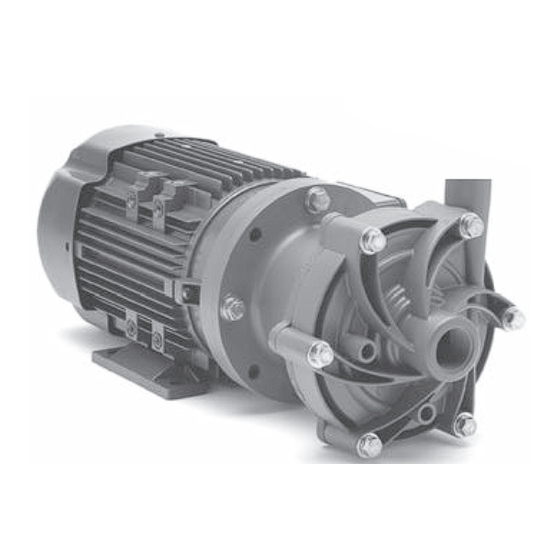
- Page 1 DB6, 6H, 7, 8, 9, 10 Series Centrifugal Pumps Assembly, Installation and Operation Manual...
- Page 2 EU Declaration of Conformity Finish Thompson Inc. hereby declares that the following machine(s) fully comply with the applicable health and safety requirements as specified by the EC Directives listed. The product may not be taken into service until it has been established that the drive motor for the centrifugal pump complies with the provisions of all relevant EC Directives.
-
Page 3: Table Of Contents
Spare Parts Diagram ........................9 Spare Parts List ..........................10-12 Impeller Assemblies ......................... 13 NOTE: Maintenance videos are now available on-line at www.finishthompson.com. FTI Contacts: Tech Service: 800-888-3743 or techservice@finishthompson.com Order Fax: 814-459-3460 or 814-455-8518 Sales: 814-455-4478; 800-934-9384 (U.S. & Canada) -
Page 4: Important Information - Read Me First
You must select an explosion-proof FTI motor or provide your own explosion-proof motor. When pumping non-flammable or non-combustible liquids in a hazardous area using a DB Series pump, it is important to take these guidelines: You must select the non-sparking (Ns) bronze bump ring option. -
Page 5: Installation/Operation Precautions
WARNING: The pump and associated components are heavy. Failure to properly support the pump during lifting and movement could result in serious injury or damage to the pump and components. WARNING: Never run pump at less than minimum flow or with the discharge valve closed. This could lead to pump failure. Installation/Operation Precautions CAUTION: This pump should never be operated without liquid in the casing. -
Page 6: Unpacking And Inspection
Unpacking and Inspection Unpack the pump and examine for any signs of shipping damage. If Secure the drive on the motor shaft. any damage is detected, save the packaging and notify the carrier WARNING: Be careful, magnets will immediately. try to attract tools. Section I - Assembly Metric Motors: Secure the drive to the motor shaft using bolt, lock washer and... -
Page 7: Section Ii - Installation Mounting
Section II – Installation installed ¼” drain in the impeller housing. See the Drain Installation Section for details. Mounting · For units in a suction lift system, install appropriate piping in the Motor feet should be securely fastened to a solid foundation. discharge to allow priming of the pump (DB models are not self- Note: Shims are required for the motor feet on ALL 63, 71 and 80 priming). -
Page 8: Flush Systems
magnet and impeller assembly away from metal chips or particles. Flush Systems Stop the pump, lock out the motor starter, close all the valves that CAUTION: Some fluids react with water; use compatible flushing are connected to the pump, and drain/decontaminate the pump. fluid. -
Page 9: Outer Drive Replacement
Remove the impeller shaft (item 6) from the barrier and check for signs of cracking, chipping, scoring or wear. See figure 15. Remove the barrier (item 7) from the Figure 22 motor adapter (item 11) (make sure Figure 20 Figure 21 the shaft has been removed). -
Page 10: Section Vii - Troubleshooting
Suction lift too high or insufficient NPSH the pump model to avoid error. • Clogged suction line or impeller vanes Other FTI Products • Motor rotation incorrect (correct rotation when viewed from the See our full product range at www.finishthompson.com. -
Page 11: Part Number Explanation
PART NUMBER EXPLANATION BASE MODEL ALTERNATIVE COMPONENTS Code COMPONENTS 1. Select base model (E.G. DB10P*) PTFE Bushing Graphite Carbon Alumina Ceramic* 2. If standard components are not suitable, enter symbol(s) of alternative compo nents EPDM in any order. O-Ring Simriz* Base Model - -__-__-_______ Kalrez*... -
Page 12: Spare Parts Diagram
DB 6 - 10 SPARE PARTS DIAGRAM... -
Page 13: Spare Parts List
DB 6 - 10 SPARE PARTS LIST DB6/6H/9 DB7/10 Pump Material Pump Material Pump Material Item Description Polypro PVDF Polypro PVDF Polypro PVDF Housing w/ Ring NPT threads & standard ceramic ring 106265 106265-1 106337 106337-1 106252 106252-1 BSP threads & standard ceramic ring 106265-2 106265-3 106337-2... - Page 14 DB 6 - 10 SPARE PARTS LIST - Cont. DB6/6H/9 DB7/10 Item Qty Description Pump Material Pump Material Pump Material Polypro PVDF Polypro PVDF Polypro PVDF Clamp Ring Standard 106246 106246-1 106246 106246-1 106246 106246-1 Bronze Ring 106521 106521-1 106521 106521-1 106521 106521-1...
- Page 15 Hardware - All DB6-10 Models Item Description Stainless Steel Titanium Housing Bolt J102789 106308 Housing Lock Washer J102282 J103847 Housing Flat Washer 105767 105768 Clamp Ring Flatwasher 105767 105768 Clamp Ring Lockwasher J102282 J103847 Clamp Ring Bolt 105770 105771 Drive Bolt (IEC Motors Only) 63 frame 106314 106315...
-
Page 16: Impeller Assemblies
Impeller Assemblies Thrust Ring Impeller Model Material Material Impeller Diameter (in.) 3.00 2.75 2.50 3.50 3.25 3.00 2.75 Polypro 106356-4 106356-6 106356-8 106356 106356-2 106356-4 106356-6 PTFE PVDF 106356-5 106356-7 106356-9 106356-1 106356-3 106356-5 106356-7 Polypro 106357-4 106357-6 106357-8 106357 106357-2 106357-4 106357-6...
Need help?
Do you have a question about the 10 Series and is the answer not in the manual?
Questions and answers