
Related Manuals for Steel City 60100

Summary of Contents for Steel City 60100
-
Page 1: User Manual
User Manual Read and understand this manual before using machine. MINI LATHE Model Number 60170 (5-Speed) Model Number 60100 (Variable Speed) ® STEEL CITY TOOL WORKS Manual Part No. OR71661... -
Page 3: Table Of Contents
The drawings, illustrations, photographs, and specifications in this user manual represent your machine at time of print. However, changes may be made to your machine or this manual at any time with no obligation to Steel City Tool Works. -
Page 4: Warranty
2 YEAR LIMITED WARRANTY Steel City Tool Works, LLC (SCTW) warrants this SCTW machinery to be free of defects in workmanship and materials for a period of 2 years from the date of the original retail purchase by the original owner for domestic use. Granite components are warranted for 2 years based on normal use and is void if non SCTW accessories are used that cause the break or chip. -
Page 5: Warranty Card
City:______________________________________________ Online: ______________________________________________ ___ Vacuum Veneer Press ___ Wide Belt Sander Other____________________________________________ How did you first learn of Steel City Tool Works? ___ Advertisement ___ Mail Order Catalog 11. Which benchtop tools do you own? Check all that apply. ___ Web Site... - Page 6 FOLD ON DOTTED LINE PLACE STAMP SteelCityToolWorks #4 Northpoint Court Bolingbrook, IL 60440 FOLD ON DOTTED LINE...
-
Page 7: Product Specifications
PRODUCT SPECIFICATIONS 60100 Mini Lathe 60170 Mini Lathe Variable Speed 5-Speed MOTOR Continuous Duty HP 1/2 HP 1/2 HP Amps Voltage 115V DC 115V AC Phase Single Single Hertz 60 Hz 60 Hz 500-3800 1725 SPECIFICATIONS Swing Over Bed 10”... -
Page 8: Accessories And Attachments
ACCESSORIES AND ATTACHMENTS There are a variety of accessories available for your Steel City Product. For more information on any accessories associated with this and other machines, please contact your nearest Steel City distributor, or visit our website at: www.steelcitytoolworks.com. -
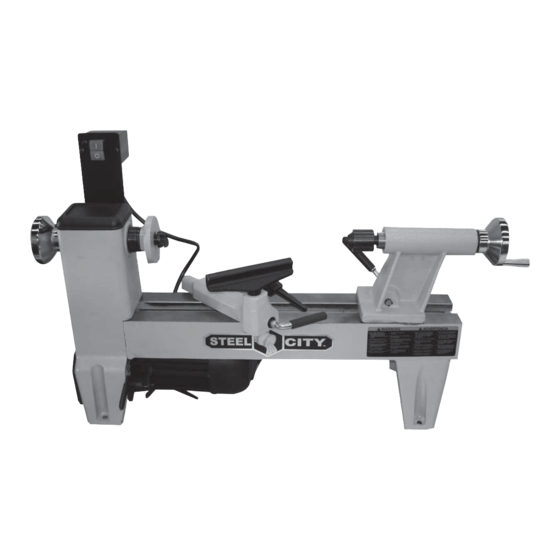
Page 9: Feature Identification
FEATURE IDENTIFICATION Model Number 60100 (Variable Speed) A) Headstock B) Variable Speed Switch C) Faceplate D) Drive center spindle E) Tool rest F) Tailstock spindle G) Handwheel H) Banjo lock handle Motor plate lever J) Banjo K) Tool rest lock handle L) Motor plate locking handle M) ON/OFF Switch N) Tailstock... - Page 10 FEATURE IDENTIFICATION Model Number 60170 (5-Speed) Headstock ON/OFF switch Faceplate Drive center spindle Tool rest Tailstock spindle Handwheel Banjo lock handle Banjo Motor plate lever Tool rest lock handle AA) Tailstock BB) Bed...
-
Page 11: General Safety
GENERAL SAFETY WARNING WARNING TO AVOID serious injury and damage to the machine, read and follow all Safety and Operating Instructions before assembling and operating this machine. This manual is not totally comprehensive. It does not Exposure to the dust created by power sanding, saw- and can not convey every possible safety and opera- ing, grinding, drilling and other construction activities tional problem which may arise while using this... - Page 12 11. DO NOT FORCE the machine to perform an opera- WARNING tion for which it was not designed. It will do a safer and higher quality job by only performing operations for which the machine was intended. 12. DO NOT stand on a machine. Serious injury could result if it tips over or you accidentally contact any 3.
-
Page 13: Product Safety
Obtain advice from supervisor, 10. USE accessories only recommended by Steel City. instructor, or another qualified individual who is 11. DO NOT pull the mini lathe by the power cord. - Page 14 15. ALWAYS rotate the workpiece by hand after 28. ALWAYS use safety glasses. Also use face or dust installing on the faceplate. masks if the cutting operation is dusty. Everyday eyeglasses only have impact resistant lenses, they 16. DO NOT mount a split workpiece or one containing are NOT safety glasses.
-
Page 15: Electrical Requirements
ELECTRICAL REQUIREMENTS TO REDUCE the risk of electrical shock, DO NOT use WARNING machine outdoors. DO NOT expose to rain. Store indoors in a dry area. TO PREVENT electrical shock, follow all electrical and safety codes, including the National Electrical Code DO NOT connect the machine to the power source (NEC) and the Occupational Safety and Health before you have completed the set up process. - Page 16 EXTENSION CORDS Fig. 1-1 WARNING To reduce the risk of fire or electrical shock, use the proper gauge of extension cord. When using an extension cord, be sure to use one heavy enough to carry the current your machine will draw. The smaller the gauge-number, the larger the diameter of the extension cord is.
-
Page 17: Unpacking & Inventory
“ON” after all the parts have been removed completely. obtained and installed correctly. For missing parts, contact Steel City at 1-877-SC4-TOOL. Model 60170 A) Lathe E) Lock handles (2) - Page 18 Model 60100 A) Lathe E) Lock handles (2) B) Switch F) Tailstock spindle C) Special wrench G) Drive center spindle D) Tool rest H) Knock-out rod...
-
Page 19: Assembly
ASSEMBLY The Mini Lathe requires very little assembly as most TOOL REST components are already installed right out of the box. 1. Insert tool rest (A) into banjo (B). SEE FIG 2. SWITCH ASSEMBLY 2. Thread lock handle (C) into banjo and tighten until the tool rest is secure. -
Page 20: Adjustments
Using a hammer and a block of wood, tap the tail- Fig. 4 stock spindle to set it in the tailstock. 3. Thread lock handle (C) into the tailstock and tighten. SEE FIG 4. ADJUSTMENTS ADJUSTING THE TOOL REST 3. If the banjo will not tighten securely using the banjo lock handle, see ADJUSTING CLAMPING The tool rest should be positioned as close as possible PRESSURE. -
Page 21: Section 12 Operations
3. Replace tailstock and/or banjo and recheck clamp- Fig. 8 ing pressure. If further adjustment is necessary, repeat steps 1 and 2. REMOVING SPINDLES A knockout rod is provided to remove either the drive center spindle from the headstock or the tailstock spin- dle from the tailstock. - Page 22 CHANGING SPINDLE SPEEDS Fig. 11 (MODEL 60170 ONLY) THIS SECTION ONLY APPLIES TO THE 5 SPEED MINI LATHE, MODEL 60170. FOR INFORMATION ON CHANGING SPEEDS ON THE VARIABLE SPEED MINI LATHE, MODEL 60100, REFER TO THE CHANGING SPINDLE SPEEDS SECTION THAT FOLLOWS THIS SECTION.
-
Page 23: Changing Spindle Speeds
Make certain that the belt is aligned with TION ON CHANGING SPEEDS ON THE 5 SPEED the motor pulley and the spindle pulley. MINI LATHE, MODEL 60170, REFER TO THE SEE FIG. 14. CHANGING SPINDLE SPEEDS SECTION THAT PRE- CEDES THIS SECTION. - Page 24 Fig. 15 The Speed Control Knob(B) sets the speed of the lathe to suit the weight of the workpiece or the type of tool being used. After the lathe is started, turn the knob clockwise to increase the speed , turn counterclockwise to reduce the speed.
-
Page 25: Operations
1. Turn variable Speed knob to it’s lowest setting. 5. Turn the lathe ON. When first starting out, make (This applies to Model 60100 only. Model 60170 sure that lathe is set to run at its slowest speed. As Owners can skip this step.) you become more comfortable and gain experience 2. -
Page 26: Maintenance
MAINTENANCE CLEANING Fig. 16 WARNING With the machine unplugged, blow off motor with low pressure air to remove dust or dirt. Air pressure above 50 P.S.I. should not be used as high-pres- sured air may damage insulation. The operator should always wear a respirator and eye protection when using compressed air. - Page 27 2. Loosen the motor plate lock handle (C) and lift up Fig. 18 on the motor plate handle (D) to take tension off of the belt. SEE FIG 18. 3. Locate the set screw on the spindle pulley and loosen the set screw. 4.
-
Page 28: Troubleshooting
3. Broken belt. 3. Replace belt. 4. Worn spindle bearings. 4. Replace bearings. 5. Capacitor is bad (Model 60170 only) 5. Replace the capacitor (Model 60170 only). 6. Brushes are bad (Model 60100 only) 6. Replace brushes (Model 60100 only). - Page 29 N NOTES N...
-
Page 30: Parts List
PARTS... - Page 31 PART PART DESCRIPTION QTY. DESCRIPTION QTY. OR71600 SIDE COVER OR71637 HANDLE SLEEVE OR71601 SPRING CLAMP OR71624 HANDLE ASSY OR71602 HINGE OR71664 TAIL STOCK OR94190 ST3.5X9.2 FL HD TAP SCREW OR94200 EXT RET RING OR71603 HEAD STOCK HANDWHEEL, INCL REF 6 OR71665 SCR SHAFT OR90222...
- Page 32 N NOTES N...
- Page 33 N NOTES N...
- Page 34 N NOTES N...
- Page 35 5 Year Warranty...
Need help?
Do you have a question about the 60100 and is the answer not in the manual?
Questions and answers