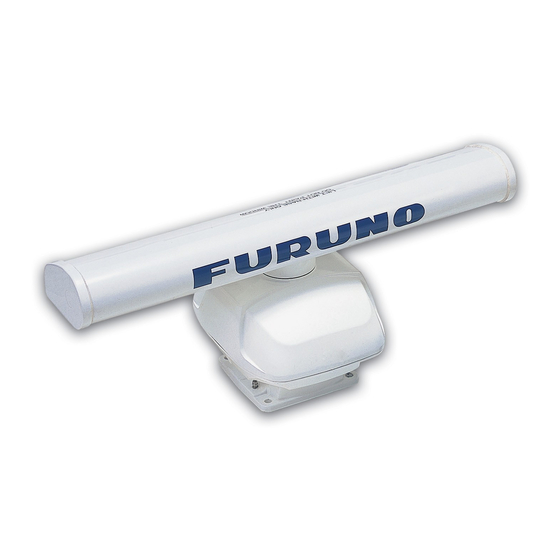
Table of Contents
Advertisement
DRS4A/DRS6A/DRS12A/DRS25A
SAFETY INSTRUCTIONS ............................................................................ i
SYSTEM CONFIGURATION ....................................................................... ii
EQUIPMENT LISTS.................................................................................... iv
1. MOUNTING ............................................................................................ 1
1.1
Mounting Considerations ..............................................................................................1
1.2
Mounting Procedure for DRS2D/4D ............................................................................. 2
1.3
Mounting Procedure for DRS4A/6A/12A/25A ...............................................................3
1.4
Mounting of Power Supply Unit PSU-013 (for DRS25A)/PSU-012 (Option) ................8
2. WIRING .................................................................................................. 9
2.1
Wiring inside DRS2D/4D ............................................................................................12
2.2
Wiring inside DRS4A/6A/12A/25A ..............................................................................16
2.3
Wiring inside Power Supply Unit PSU-013 (for DRS25A) .......................................... 20
2.4
Wiring inside Power Supply Unit PSU-012 (Option)................................................... 21
PACKING LISTS...................................................................................... A-1
OUTLINE DRAWINGS............................................................................. D-1
INTERCONNECTION DIAGRAMS.......................................................... S-1
Installation Manual
RADAR SENSOR
www.furuno.co.jp
DRS2D/DRS4D/
Advertisement
Table of Contents

Summarization of Contents
Radar Sensor Safety Instructions
RF Radiation Safety and Distances
Information on RF radiation hazards, safe distances, and precautions.
Compass Safe Distance Guidelines
Table showing safe distances for magnetic compasses to prevent deviation.
Radar System Configuration Diagrams
System Diagram for DRS2D/4D/4A/6A/12A
Diagram illustrating system connections for DRS2D, 4D, 4A, 6A, and 12A models.
System Diagram for DRS25A
Diagram showing system connections for the DRS25A radar sensor.
Radar Sensor Equipment and Parts Lists
Standard Supply Components
List of standard equipment included with the radar sensor.
Optional Supply Components
List of optional equipment available for the radar sensor.
Installation Materials Details
Detailed list of materials required for installation, including part numbers and specifications.
Radar Sensor Mounting Procedures
Mounting Location Considerations
General guidelines for selecting an optimal location for radar sensor installation.
Mounting Procedure for DRS2D and DRS4D
Step-by-step instructions for mounting the DRS2D/4D radar sensor.
Mounting Procedure for DRS4A/6A/12A/25A
Instructions for mounting DRS4A, DRS6A, DRS12A, and DRS25A radar sensors.
Power Supply Unit (PSU-012/013) Mounting
Guidelines for installing the PSU-013 and PSU-012 power supply units.
Radar Sensor Wiring Instructions
Internal Wiring for DRS2D/4D
Detailed steps for internal wiring of the DRS2D/4D radar sensor.
Internal Wiring for DRS4A/6A/12A/25A
Procedures for internal wiring of DRS4A, DRS6A, DRS12A, and DRS25A sensors.
Wiring for PSU-013 Power Supply Unit
Instructions for wiring the PSU-013 power supply unit for DRS25A.
Internal Wiring for PSU-012 Power Supply Unit
Steps for internal wiring of the PSU-012 optional power supply unit.
Radar Sensor Outline and Dimension Drawings
DRS2D Outline Dimensions
Dimensional drawing for the DRS2D radar sensor.
DRS4D Outline Dimensions
Dimensional drawing for the DRS4D radar sensor.
DRS4A/6A/12A/25A Outline Dimensions
Dimensional drawing for DRS4A, DRS6A, DRS12A, and DRS25A radar sensors.
PSU-012 Outline Dimensions
Dimensional drawing for the PSU-012 power supply unit.
PSU-013 Outline Dimensions
Dimensional drawing for the PSU-013 power supply unit.
Radar Sensor Interconnection Diagrams
Interconnection Diagram for DRS2D/4D
Diagram showing the electrical connections for DRS2D and DRS4D radar sensors.
Interconnection Diagram for DRS4A/6A
Diagram illustrating electrical connections for DRS4A and DRS6A radar sensors.
Interconnection Diagram for DRS12A
Diagram showing electrical connections for the DRS12A radar sensor.
Interconnection Diagram for DRS25A
Diagram illustrating electrical connections for the DRS25A radar sensor.


Need help?
Do you have a question about the NAVnet 3D DRS6A and is the answer not in the manual?
Questions and answers