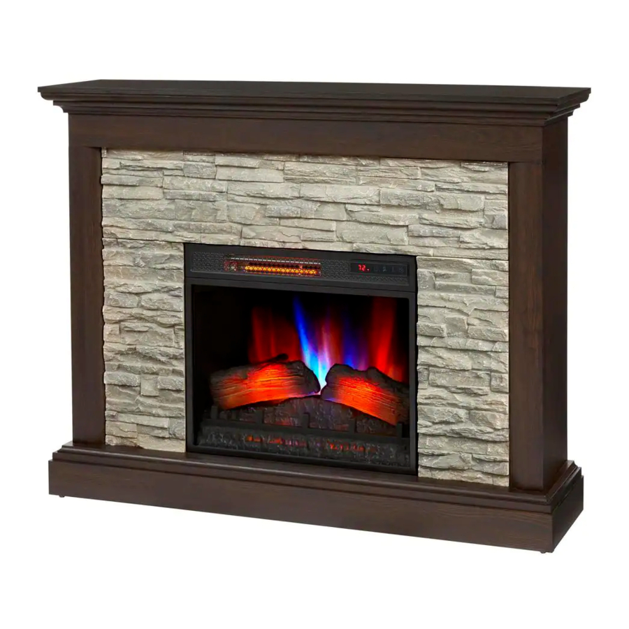
HOMEDEPOT Home Decorators WHITTINGTON Manual
- Use and care manual (24 pages)
Advertisement
Maximum Load Warning


This unit is intended for use only with the products and maximum weights indicated. Use with other products or products heavier than the maximum weights indicated may result in instability causing possible injury.
Pre-Assembly
HARDWARE INCLUDED

| Part | Description | Part Number | Quantity |
| AA | Screw- 3 x 12 mm | PH-SCRBLK007 | 2 |
| BB | Bolt- 6.3 x 32 mm | PH-BLTBLK001 | 11 |
| CC | Flat Washer | PH-WSRBLK001 | 11 |
| DD | Wood Dowel | PH-DWLNTL001 | 26 |
| EE | Cam Lock Screw | PH-KDBZNC001 | 17 |
| FF | Cam Lock Connector | PH-KDCZNC001 | 17 |
| GG | Screw- 4 x 50 mm | PH-SCRBLK006 | 10 |
| HH | Screw- 3.5 x 12 mm | PH-SCRBLK013 | 6 |
| II | Bolt- 6.3 x 12 mm | PH-BLTBLK002 | 28 |
| JJ | Plastic Connector Block | PH-PCXXX005 | 14 |
| KK | Tipping Restraint Hardware | PH-BKTWHT003 | 1 |
| LL | Threaded Insert Screw (Pre-attached) | PH-THRZNC001 | 11 |
| MM | Floor Glide (Pre-attached) | PH_GLDBRW001 | 4 |
| NN | Metal Plate (Pre-attached) | PH-PLTBLK001 | 2 |
 NOTE: Hardware not shown to actual size.
PRODUCT SPECIFICATIONS
| VOLTAGE | 120VAC, 60 Hz |
| AMPS | 12.5 Amps |
| WATTS | 1500 Watts |
PLANNING ASSEMBLY
Before beginning assembly of product, make sure all parts are present. Compare parts with Hardware Included and Package Contents lists. If any part is missing or damaged, do not attempt to assemble, install or operate the product. Contact customer service for replacement parts. Estimated Assembly Time: 90 Minutes
TOOLS REQUIRED
Phillips Screwdriver

PACKAGE CONTENTS

NOTE: All panels are labeled left and right as viewed from the front of unit.
| Part | Description | Quantity |
| A | Bottom Shelf | 1 |
| B | Left Surround Panel | 1 |
| C | Right Surround Panel | 1 |
| D | Top Surround Panel | 1 |
| E | Left Decorative Surround Panel | 1 |
| F | Right Decorative Surround Panel | 1 |
| G | Top Panel | 1 |
| H | Top Decorative Surround Panel | 1 |
| I | Left Side Panel | 1 |
| J | Right Side Panel | 1 |
| K | Base Left Side Rail | 1 |
| L | Base Right Side Rail | 1 |
| M | Base Back Rail | 1 |
| N | Base Front Rail | 1 |
| O | Fireplace Insert | 1 |
Assembly
- Preparing the surround panel

- Locate the Top Surround Panel (D).
- Insert the Wood Dowels (DD) into the pre-drilled holes on the edge of the Top Surround Panel where indicated.
- Locate the Left Surround Panel (B) and the Right Surround Panel (C).
- Align pre-drilled holes at the top edge of each panel (B, C) with the previously installed wood dowels on the Top Surround Panel (D).
- Assembling the front surround

- Locate the Left Decorative Surround Panel (E) and Right Decorative Surround Panel (F).
- Align pre-drilled holes of each Panel (E, F) with the inner edges of the surround assembly.
- Place one Washer (CC) over the top of each pre-drilled hole.
- Secure one Bolt (BB) through each Washer (CC) in each pre-drilled hole.
- Attaching decorative surround panels

- Locate the Top Decorative Surround Panel (H).
- Insert the Wood Dowels (DD) into the pre-drilled holes along the edge of the Top Decorative Surround Panel (H) where indicated.
- Align the pre-drilled holes at the edges of each Decorative Surround Panel (E, F) with the previously installed Wood Dowels (DD) on the Top Decorative Surround Panel (H).


- Attaching the surround bracket

- Find the pre-attached Metal Plates (NN) located on the Top Decorative Surround Panel (H).
- Rotate each bracket to span across the edges of each Decorative Surround Panel (E, F).
- Secure each bracket with a Screw (AA).
- Securing the surround assembly

- Align Washers (CC) over the pre-drilled holes of the Top Decorative Surround Panel (H).
- Secure panels in place using Bolts (BB) through each washer and into the pre-drilled holes.
- Preparing the surround for main assembly

- Insert Cam Lock Screws (EE) into the pre-drilled hole along the edges of the surround as shown. Tighten using a Phillips screwdriver.
- Insert the Wood Dowels (DD) into the pre-drilled holes where indicated.


- Attaching the side panels

- Locate the Left Side Panel (I) and the Right Side Panel (J).
- Align pre-drilled holes on the edges of each Side Panel (I, J) with the previously installed cam lock screws and wood dowels from step 6.
- Secure the cam lock screws in the Left Side Panel (I) by inserting the Cam Lock Connectors (FF) into the pre-drilled holes as shown.
- Tighten with a Phillips screwdriver.
- Repeat for the Right Side Panel (J).
- Preparing for the bottom assembly

- Insert Wood Dowels (DD) into the bottom edges of the main assembly as indicated.
- Preparing the base panels

- Locate the Base Left Side Rail (K) and Base Right Side Rail (L).
- Insert Bolts (II) through the Two-Hole Plastic Connector Blocks (JJ) on each rail as shown.
- Tighten with the Phillips screwdriver.


- Preparing the base back panel

- Locate Base Back Rail (M) and Base Front Rail (N).
- Align Plastic Connector Blocks (JJ) with pre-drilled holes on the Base Back Rail (M) and Base Front Rail (N).
- Insert bolts (II) through the Plastic Connector Blocks (JJ) as shown.
- Tighten with the Phillips screwdriver.
- Connecting the base panels

- Align the Base Left Side Rail (K) with the Base Back Rail (M) and push together.
- Secure the Panels (K, M) using a Phillips screwdriver. Screw the Bolts (II) through pre-installed plastic connector blocks.
- Repeat to attach the Base Right Side Rail (L).


- Attaching the front base panel

- Align the Front Base Rail (N) with the previously assembled base rails. Secure with Bolts (II) through the Plastic Connector Blocks (JJ) using a Phillips screwdriver.
- Assembling the base

- Locate the Bottom Shelf (A).
- Attach the previously assembled base rails to the Bottom Shelf (A) by inserting Bolts (II) through the Plastic Connector Blocks (JJ). Tighten with a Phillips screwdriver.


- Attaching the base

- Align the Bottom Shelf (A) with the center assembly.
- Insert Screws (GG) through the bottom of the Bottom Shelf (A) and securely tighten using a Phillips screwdriver.

- Preparing the top of the assembly

- Insert Wood Dowels (DD) into the pre-drilled holes in the top edges of the main assembly.
- Preparing the top panel for assembly

- Locate the Top Panel (G) and place onto a flat surface.
- Insert the Cam Lock Screws (EE) into the pre-drilled holes in the bottom of the Top Panel (G). Tighten using a Phillips Screwdriver.


- Attaching the top panel

- Place the Top Panel (G) onto the main assembly by aligning the previously installed cam lock screws and wood dowels with the pre-drilled holes.
- From underneath to the Top Panel (G), secure the cam lock screws by inserting Cam Lock Connectors (FF) into the pre-drilled holes. Tighten using a Phillips Screwdriver.

- Installing the fireplace insert
![]()
- Lift the Fireplace Insert (O) carefully into the back of the unit and center in the fireplace insert opening.
- Do not drag the fireplace insert across the base as it may scratch your unit.
- Reinforcing the insert assembly

- Secure the electric fireplace to the surround panels using Screws (HH). Tighten on both sides using a Phillips screwdriver.


- Installing the tipping restraint hardware

- When the Tipping Restraint Hardware (KK) is properly installed, it can provide protection against unexpected tipping of the Unit due to small tremors, bumps or climbing.
- Each Tipping Restraint Hardware (KK) includes one Unit Anchor, one Wall Anchor, one Anchor Tether, and four Anchor Screws. Use these to complete the following steps for a proper installation.
- Locate a secure wall stud behind the unit closest to left side.
- Align the Unit Anchor with a wall stud and attach with two Anchor Screws using a Philips Screwdriver. The Anchor Screws must pass through the Top Assembly (G) for proper installation.
- Align the Wall Anchor in the center of the wall stud, at level with the Unit Anchor, and attach with two Anchor Screws using a Philips Screwdriver.
- On the Anchor Tether, detach the cable from the connector and loop the loose cable through the eyelets on the Wall Anchor and Unit Anchor. Reattach the loose cable to the connector, but do not tighten.
- Locate a secure wall stud behind the unit closest to the right side, and repeat the steps above.
- Tighten both Anchor Tethers by pulling the cable the through connector.

NOTE: Installation of the Tipping Restraint Hardware (KK) will provide a small space between the wall and the unit. This will allow you to run power cords and connector cables to your television or other devices placed on top of the Unit.

Installing the Tipping Restraint Hardware will help prevent accidents or damage to the unit.
Operation
NOTE: The control panel can be accessed at the upper-right corner of the insert.

- Powering the fireplace
- Push the Power button to supply power to all functions of the fireplace and put the insert in a standby mode.
- Push the Power button again to turn off all functions.
![information]() NOTE: All previous settings are held in memory, so the next time you power up the fireplace, the unit will turn on with the same settings.
NOTE: All previous settings are held in memory, so the next time you power up the fireplace, the unit will turn on with the same settings.
![information]() NOTE: Holding the Power button on the control panel for 10 seconds will disable the heater function.
NOTE: Holding the Power button on the control panel for 10 seconds will disable the heater function.
![]()

- Adjusting the flame
- There are 5 brightness levels that can be selected and OFF (00) setting. Settings F5 - F1 decrease in brightness.
![]()
- There are 5 brightness levels that can be selected and OFF (00) setting. Settings F5 - F1 decrease in brightness.

- Adjusting the heater
- The fireplace contains three infrared quartz heating elements.
- The thermostat setting range is 62°F - 82°F (17°C - 27°C) or continuously ON. Set the heater to (00) to use the flame effects without the heat.
- The thermostat is adjustable by 2°F or 1°C increments. The "
![]() " buttons on the control panel and " +/- " buttons on the remote control will increase / decrease temperature setting.
" buttons on the control panel and " +/- " buttons on the remote control will increase / decrease temperature setting.
![information]() NOTE: To change between °F and °C press and hold the TIMER button on the control panel for 3 seconds.
NOTE: To change between °F and °C press and hold the TIMER button on the control panel for 3 seconds.
![]()


- Setting the timer
- Pressing the Timer button will cycle through the timer settings; 30 minutes, 1 Hour, 2H, 3H, 4H, 5H, 6H, 7H, 8H, 9H and off (00).
![]()
- Pressing the Timer button will cycle through the timer settings; 30 minutes, 1 Hour, 2H, 3H, 4H, 5H, 6H, 7H, 8H, 9H and off (00).
- Adjusting the flame speed
- Each flame color option has speed options available. Setting S1 is slowest ranging up to setting S5 which is the fastest.
![]()
- Each flame color option has speed options available. Setting S1 is slowest ranging up to setting S5 which is the fastest.


- Replacing the remote control battery
- When the remote control stops operating or its range seems reduced, it is time to replace the batteries with new ones.
- On the back end of the remote, press and slide the battery door open and remove the old battery.
- Insert 2 AAA batteries, checking that the + and - sides of the battery match inside the battery compartment.
- Replace the battery compartment door.
![information]() NOTE: Do not mix old and new batteries. Do not mix alkaline, standard (carbonzinc), or rechargeable (nicad, nimh, etc) batteries. Do not ingest batteries.
NOTE: Do not mix old and new batteries. Do not mix alkaline, standard (carbonzinc), or rechargeable (nicad, nimh, etc) batteries. Do not ingest batteries.
![information]() NOTE: Please operate the remote control at a slow measured pace. Press the remote control buttons with an even motion and gentle pressure. Repeatedly pressing buttons in rapid succession may cause the transmitter to malfunction.
NOTE: Please operate the remote control at a slow measured pace. Press the remote control buttons with an even motion and gentle pressure. Repeatedly pressing buttons in rapid succession may cause the transmitter to malfunction.
![information]() NOTE: Batteries should be removed if the product is to be left unused for a long time.
NOTE: Batteries should be removed if the product is to be left unused for a long time.
- Power cord information
![]()
- This heater is for use on 120 volts. The cord has a plug as shown in the figure.
- Connect to properly grounded outlets only.
- Do not use a 2 prong adapter. Never use with an extension cord or relocatable power tap (outlet/ power strip).
- Patented Safer Plug® information
![]()
- This product is equipped with a Safer Plug®, which is an advanced safety device that helps detect electrical fires caused from faulty outlets.
- Overloading of outlets, adapters and surge protectors may cause overheating, damage, and increased risk of fires. The Safer Plug continuously monitors the temperature in the plug and outlet and will turn off the heater to prevent unsafe outlet overheating.
- If the Safer Plug cuts the power due to unsafe conditions it will show an " Er " message on the screen. If this occurs the Safer Plug has prevented
- a potentially unsafe condition. To reset the device if this occurs, first allow the plug to cool down. Once the plug has cooled down, unplug the device and wait 5 seconds, then plug back in and continue to use normally.
- If the Safer Plug continues to activate, your outlet may be faulty. Check your heater cord and plug connections. Faulty wall outlet connections or loose plugs can cause the outlet or plug to overheat. Be sure the plug fits tight in the outlet. Heaters draw more current than small appliances. Overheating of the outlet may occur even if it has not occurred with the use of other appliances. During use check frequently to determine if your plug outlet or faceplate is HOT! If so, discontinue use of the heater and have a qualified electrician check and/or replace the faulty outlet(s).


Care and Cleaning
- Dust your fireplace regularly with a soft non-lint-producing cloth or household dusting product. Clean your fireplace with a gentle non-abrasive household cleaner. Dry your fireplace immediately with a soft cloth or towel.
- The motors used on the fan and the flame generator assembly are pre-lubricated for extended bearing life and require no further lubrication. However, we recommend periodic cleaning/vacuuming of the fan/heater. Make sure the unit is turned OFF and unplugged whenever you are cleaning the heater or fireplace.
Make sure the power is turned off before proceeding with repairs. Any electrical repairs or rewiring of this unit should be carried out by a licensed electrician in accordance with national and local codes. If repairing or replacing any electrical component or wiring, the original wire routing, color coding and securing locations must be followed. During any service of this appliance, the power to the unit must be turned off. First turn the main power switch to the OFF position. Then remove the electrical plug from the wall outlet.

Electrical outlet wiring must comply with local building codes and other applicable regulations to reduce the risk of fire, electrical shock and injury to persons.
Do not use this fireplace if any part of it has been under water. Immediately call a qualified service technician to inspect the fireplace and replace any part of the electrical system.
Disconnect power before attempting any maintenance or cleaning to reduce the risk of fire, electrical shock or personal injury.
Troubleshooting
| PROBLEM | ROOT CAUSE | CORRECTIVE ACTION |
| Fireplace stopped heating before reaching the desired temperature. | Fireplace has reached set temperature. Temperature around fireplace might be a few degrees higher than other area in the room. | Set Fireplace to a higher temperature or always "on". |
Display shows " " " | The thermostat sensor is broken or disconnected. | Unplug the fireplace, remove the back panel of the fireplace and check that the thermostat is plugged into the main circuit board. If this does not solve the problem contact customer service for a replacement thermostat sensor. |
Display shows " " " | The thermostat sensor short circuited. | Contact customer service for a replacement thermostat sensor. |
Display shows " " " | Manual Reset overheat protection has triggered. | Inspect the heater and check that the air inlets and outlets are not blocked as this may cause overheating. Unplug the heater for 30 minutes and allow it to cool down. Replug and operate. Monitor the heater for signs of overheating. If the problem persists, discontinue use of the heater and contact customer service. |
Display shows " " " | Power cord overheating protection has activated. | Check your heater cord and plug connections. Faulty wall outlet connections or loose plugs can cause the outlet or plug to overheat. Be sure the plug fits tight in the outlet. Heaters draw more current than small appliances. Overheating of the outlet may occur even if it has not occurred with the use of other appliances. During use check frequently to determine if your plug outlet or faceplate is HOT! If so, discontinue use of the heater and have a qualified electrician check and/or replace the faulty outlet(s). |
Heater does not blow warm air | The heater is in a cool down cycle. | Normal operation will continue to run for about 15 seconds before shutting down. Times will vary based on temperatures. During this time cool air will blow. |
| There is no power and the logs do not glow | There is no power to the unit. | Check that the unit is plugged into a standard 120V outlet. Press the Power button several times and make sure power is set to the "ON"position. |
| The logs are not glowing, and there is no flame effect | The flame effect turned off. | Press the Flame button several times. |
| Flame effect works but heater function does not and the emberbed flashes when the Heater button is pressed | The heater is disabled. | With the power on press and hold the POWER button on the control panel for 10 seconds. Once re-enabled the emberbed lights will flash multiple times. |
The remote control is not working | There are no batteries. | Change the remote batteries. |
| The signal is poor. | Operate remote transmitter at a slow measured pace. Press the remote control buttons with an even motion and gentle pressure. Repeatedly pressing buttons in rapid succession may cause the transmitter to malfunction. | |
| The remote is too far from the heater. | Operate the remote at a distance less than 20 ft from the front of the appliance; point the remote at the control panel. |
Replacement Parts
For replacement parts, call our customer service department at 1-800-998-7021, 8 a.m.-7 p.m., EST, Monday-Friday, 9 a.m. - 6 p.m., EST, Saturday.
| Part | Description | Qty. |
| 1 | Flame Circuit Board | 1 |
| 2 | Flame Generator Driver Mode | 1 |
| 3 | EmberBed with Log Set | 1 |
| 4 | Control Panel Circuit Board | 1 |
| 5 | Main Circuit Board | 1 |
| 6 | Thermostat Sensor | 1 |
| 7 | Blower / Heater Assembly | 1 |
| 8 | Front Glass Assembly | 1 |
| 9 | Remote Control | 1 |

Safety Information
Please read and understand this entire manual before attempting to assemble, operate or install the product. If you have any question regarding the product, please call customer service at 1-800-988-7021, 8 a.m.-7 p.m., EST, Monday-Friday, 9 a.m. - 6 p.m., EST, Saturday.
When using electrical appliances, basic precautions should always be followed to reduce the risk of fire, electrical shock, and injury to persons including the following:
- Read all instructions before using this appliance.
- If possible, always unplug this appliance when not in use.
- Only a qualified service person should repair this product.
- Do not use outdoors.
- Do not cover the cord under the carpeting. Do not cover with throw rugs, runners or the like. Arrange the cord away from traffic areas and where it will not be tripped over.
- To disconnect this appliance, turn the controls to the off position, and then remove the plug from the outlet.
- Connect to properly grounded outlets only.
- This appliance, when installed, must be electrically grounded in accordance with local codes or, in the absence of local codes, with the current CSA C22.1 Canadian Electrical Code. For U.S.A. installations, follow local codes and the National Electrical Code, ANSI/NFPA NO.70.
- This appliance has hot and arcing or sparking parts inside. Do not use it in areas where gasoline, paint or flammable liquids are used or stored. This fireplace should not be used as a drying rack for clothing. Do not hang Christmas stockings or other decorations on or near this product.
- There is a thermostat limiter inside the heater. When inner temperature overheating or abnormal heating occurs, the thermostat protective device will cut off the power supply to avoid damage to the fireplace or risk of fire.

High temperatures may be generated under certain abnormal conditions. Do not partially or fully cover or obstruct the front of this heater.
In order to avoid overheating, do not cover the heater.
If the supply cord is damaged, it must be replaced by the manufacturer, its service agent or similarly qualified persons in order to avoid a hazard.
Under no circumstances should this fireplace be modified. Parts that must be removed for servicing must be replaced prior to operating this fireplace again.
This heater may include a visual alarm to warn that parts of the heater are getting excessively hot. If the alarm illuminates, immediately turn the heater off and inspect for any objects on or adjacent to the heater that may have blocked the airflow or otherwise caused high temperatures to have occurred. DO NOT OPERATE THE HEATER WITH THE ALARM ILLUMINATING.
This appliance is not a toy. Supervise children playing near it.
Use extreme caution when operating heater near children and the disabled.
This heater is not intended for use in bathrooms, laundry areas and similar indoor locations. Never locate this appliance where it may fall into a bathtub or other water container.
Do not insert or allow foreign objects to enter any ventilation or exhaust opening as this may cause an electric shock or fire, or damage the appliance.
To prevent a possible fire, do not block air intakes or exhaust in any manner. Do not use on soft surfaces, like a bed, where the opening may become blocked.
Use this appliance only as described in the manual. Any other use not recommended by the manufacturer may cause fire, electric shock or injury to persons.
This appliance has hot and arcing or sparking parts inside. Do not use it in areas where gasoline, paint or flammable liquids are used or stored. This fireplace should not be used as a drying rack for clothing. Do not hang Christmas stockings or other decorations on or near this product.
Never leave the heater operating unattended. Extreme caution is necessary if unsupervised children or invalids are nearby.
Before assembly, carefully use scissors or a utility knife to cut and unwrap all parts. Make sure you do not discard the hardware.
NOTE: Use care in assembling your new fireplace. Take your time and use the hardware provided and a quality Phillips head screwdriver. Never overtighten bolts.
- Do not sit on any part of the mantel.
- It is recommended to work on a soft surface like a rug or to lay out a blanket to protect the furniture from getting scratched during the assembly process.
NOTE: To avoid injury from unexpected starting or electrical shock, do not plug the power cord into a source of power during unpacking and assembly. The cord must remain unplugged whenever you are adjusting/assembling the fireplace. If any part is missing or damaged, do not attempt to use or plug in the power cord until the missing or damaged part is correctly replaced. To avoid electric shock, use only identical replacement parts when servicing double-insulated tools.
NOTE:
SAVE THESE INSTRUCTIONS
Documents / ResourcesDownload manual
Here you can download full pdf version of manual, it may contain additional safety instructions, warranty information, FCC rules, etc.
Advertisement


Need help?
Do you have a question about the Home Decorators WHITTINGTON and is the answer not in the manual?
Questions and answers