EINHELL GC-RT 1440 M Manual
- Original operating instructions (129 pages) ,
- Operating instructions manual (29 pages) ,
- Original operating instructions (99 pages)
Advertisement
Safety regulations

When using the equipment, a few safety precautions must be observed to avoid injuries and damage. Please read the complete operating instructions and safety regulations with due care. Keep this manual in a safe place, so that the information is available at all times. If you give the equipment to any other person, hand over these operating instructions and safety regulations as well. We cannot accept any liability for damage or accidents which arise due to a failure to follow these instructions and the safety instructions.
The corresponding safety information can be found in the enclosed booklet.
Read all safety regulations and instructions. Any errors made in following the safety regulations and instructions may result in an electric shock, fire and/or serious injury.
Keep all safety regulations and instructions in a safe place for future use.
Explanation of the symbols on the machine

(Fig. 13):
![]()
Note the instructions for use!![]()
If the cable is damaged or cut, pull out the power plug from the mains immediately.![]()
Never use the equipment in damp locations.![]()
Danger from catapulted parts; keep a safe distance.![]()
Rotating tool.![]()
Wear safety goggles!![]()
Wear ear muff s!![]()
Pull the power plug before carrying out maintenance, cleaning and repair work.
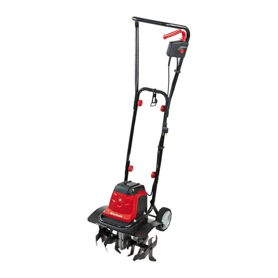
Layout and items supplied
Layout

(Fig. 1/2)
- Top push bar
- Bottom push bar
- Motor unit
- Hoe blades
- Cable strain-relief clamp
- Two-hand safety switch
- Cable securing clips
- Star nut (4x)
- Screw (4x)
- Transport wheel (2x)
- Wheel cap (2x)
Items supplied
Please check that the article is complete as specified in the scope of delivery. If parts are missing, please contact our service center or the sales outlet where you made your purchase at the latest within 5 working days after purchasing the product and upon presentation of a valid bill of purchase. Also, refer to the warranty table in the service information at the end of the operating instructions.
- Open the packaging and take out the equipment with care.
- Remove the packaging material and any packaging and/or transportation braces (if available).
- Check to see if all items are supplied.
- Inspect the equipment and accessories for transport damage.
- If possible, please keep the packaging until the end of the guarantee period.
The equipment and packaging material are not toys. Do not let children play with plastic bags, foils or small parts. There is a danger of swallowing or suffocating!
- Engine unit
- Lower push bar
- Top push bar
- Cable strain-relief clip
- Cable securing clip (2x)
- Star nut (4x)
- Screw (4x)
- Transport wheel (2x)
- Wheel cap (2x)
- Original operating instructions
- Safety instructions
Proper use
The machine is designed for digging soil (for example garden beds). Be sure to observe the restrictions in the safety instructions.
The operating instructions as supplied by the manufacturer must be kept and referred to in order to ensure that the machine is properly used and maintained. The instructions contain valuable information on operating, maintenance and servicing conditions.
For safety reasons, the machine may not be used as a drive unit for other work tools or tool sets of any kind.
The equipment is to be used only for its prescribed purpose. Any other use is deemed to be a case of misuse. The user / operator and not the manufacturer will be liable for any damage or injuries of any kind caused as a result of this.
Please note that our equipment has not been designed for use in commercial, trade or industrial applications. Our warranty will be voided if the machine is used in commercial, trade or industrial businesses or for equivalent purposes.
Technical data
Voltage: 220-240V ~ 50Hz
Power input: 1400 W
Working width: 40 cm
Hoe diameter: 20 cm
Idle speed: 280 rpm
Number of blades: 6 pieces
Sound and vibration
LpA sound pressure level: 71.71 dB(A)
KpA uncertainty: 3 dB
LWA sound power level: 91.71 dB(A)
KWA uncertainty: 3 dB
Wear ear-muffs.
The impact of noise can cause damage to hearing.
Total vibration values (vector sum of three directions) determined in accordance with EN 60745.
Vibration emission value ah ≤ 2.5 m/s2
K uncertainty = 1.5 m/s2
The specified vibration value was established in accordance with a standardized testing method. It may change according to how the electric equipment is used and may exceed the specified value in exceptional circumstances.
The specified vibration value can be used to compare the equipment with other electric power tools.
The specified vibration value can be used for initial assessment of a harmful effect.
Keep the noise emissions and vibrations to a minimum.
- Only use appliances which are in perfect working order.
- Service and clean the appliance regularly.
- Adapt your working style to suit the appliance.
- Do not overload the appliance.
- Have the appliance serviced whenever necessary.
- Switch the appliance off when it is not in use.
- Wear protective gloves.

Residual risks
Even if you use this electric power tool in accordance with instructions, certain residual risks cannot be rules out. The following hazards may arise in connection with the equipment's construction and layout:
- Lung damage if no suitable protective dust mask is used.
- Damage to hearing if no suitable ear protection is used.
- Health damage caused by hand-arm vibrations if the equipment is used over a prolonged period or is not properly guided and maintained.
Before starting the equipment
Before you connect the equipment to the mains supply make sure that the data on the rating plate are identical to the mains data.

Always pull the power plug before making adjustments to the equipment.
Assembly
(Fig. 4-11)
- Remove the Philips screw (Fig. 3/Item A) with circlip and washer from both ends of the axle.
![]()
Then push the transport wheel onto both ends of the axle as shown in Fig. 4 and secure with the Philips screw, circlip and washer (see Fig. 4 detail).
![]()
- Press the wheel caps (Fig. 5/Item 11) onto the transport wheels.
![]()
- Push the cable strain-relief clip (Fig. 6a/Item 5)
![]()
onto the lower push bar, then push the lower push bar onto the engine unit (Fig. 6a/ Item 3) as shown in Fig. 6a and secure with the screws (Fig. 6b/Item 9) and the star nuts (Fig. 6b/Item 8).
![]()
- Push the top push bar (Fig. 7a/Item 1) onto the lower push bar (Fig. 7a/Item 2) and secure with the screws (Fig. 7a/Item 9) and the star nuts (Fig. 7a/Item 8).
![]()
- Fit the two-hand safety switch on the top push bar as shown in Fig. 7b and 7c.

- Fasten the cable with the 2 cable securing clamps (Fig. 8/Item 7) to the push bars.
![]()


Power supply
The machine can be connected to any light socket-outlet (with 230 Volt alternating current). However, the socket outlet must have an earthing contact protected by a 16 A circuit breaker. Additionally, a residual current device (RCD) circuitbreaker with max. 30 mA must be used! Power cable for the device Please only use power cables that are not damaged. The total length of the power cable should not exceed 50 meters; going beyond this distance will reduce the power output of the electric motor. The power cable must have a cross-section of 3 x 1.5 mm2. The insulating sheath of such machines is frequently damaged.
Some of the causes for this are:
- Cracking due to old age of the insulation
- Kinking caused by improper fastening or guidance of the power cable
Even though power cables with damaged insulation sheaths pose a lethal hazard, some people still use them. Do not make this mistake! Cables, plugs and socket couplers must meet the following requirements listed below. Power cables used to connect machines must have a rubber insulation sheath.
The power cables must, at the very minimum, be of type HO5RN-F and 3-stranded. The cable type must be printed somewhere on the power cable. Only purchase power cables that are marked! Plugs and socket couplers for the power cables must be made from rubber and splash-proof. There is a limit to how long power cables can be. Longer power cables require larger conductor cross-sections. Power cables and connecting lines must be regularly checked for damage. Ensure that the lines are de-energized before checking them. Completely unwind the power cable. Also check power cable entry points, plugs and socket couplers for kinks.
Operation
Starting up
Connect the machine's power supply cable (Fig 9/ Item B) to the plug (Fig. 9/Item A) and secure the power cable with the strain-relief clamp (Fig 9/Item 5).

To prevent accidental start-up of the machine, the push-bar is equipped with a two-point switch (Fig. 10/Item A) which must be pressed before the lever switch (Fig. 10/Item B) can be pressed.

If the lever switch is released, the machine switches off. Repeat this process several times so that you are sure that your machine functions properly. Before you perform any repair or maintenance work on the machine, ensure that the hoe blades are not rotating and that the power supply is disconnected.
The equipment must be moved into operating position before you begin with your work. First pull the locking pin (Fig. 11/Item A) in the direction of the arrow as shown in Fig. 11 and swing up the wheel unit until the locking pin engages again in position B. Proceed in reverse order to move the equipment into transport position.

Always ensure that a safe distance (provided by the long handles) is maintained between the machine and the user. Be especially careful when changing direction on slopes and inclines. Maintain a solid footing and wear sturdy, non-slip footwear and long trousers. Always work along the incline (not up and down). Use special caution when backing up and pulling the machine (tripping hazard).
Tips for proper working
Place the machine in front of the area you wish to hoe and hold it securely on the push bar before you switch on the machine. Guide the hoe blades over the area.
To achieve cleanly hoed soil always ensure that you guide the machine in straight lines wherever possible. In so doing, the aeration swaths should always overlap each other by a few centimeters in order to avoid bare strips. Switch off the motor promptly when you arrive at the end of the area you wished to hoe. The motor must be switched off when you raise the machine (for example to change direction). Keep the underside of the machine clean and remove soil deposits. Deposits make it more difficult to start the machine and decrease the working depth. Work perpendicular to the slop on inclined areas. The machine must be switched off and the mains cable disconnected before you make any checks on the hoe blades.
The hoe blades will continue to rotate for a few seconds after the motor is switched off. Never attempt to manually stop them. In the event that the rotating hoe blade strikes an object, immediately switch off the machine and wait for the hoe blades to come to a complete stop. Then inspect the condition of the hoe blades. Replace any parts that are damaged.
Lay the power cable on the ground in front of the outlet in a figure 8. Work away from the outlet or cable and ensure that the power cable always trails in the hoed soil which will prevent the hoe blades from traveling over the cable. Replacing the power cable.
Replacing the power cable
If the power cable for this equipment is damaged, it must be replaced by the manufacturer or its after-sales service or similarly trained personnel to avoid danger.
Cleaning, maintenance and ordering of spare parts
Maintenance and cleaning work on the machine as well as removal of the safety devices may only be performed when the motor is switched off and the power cable has been pulled.
Cleaning
- Keep all safety devices, air vents and the motor housing free of dirt and dust as far as possible. Wipe the equipment with a clean cloth or blow it with compressed air at low pressure.
- We recommend that you clean the device immediately each time you have finished using it.
- Clean the equipment regularly with a moist cloth and some soft soap. Do not use cleaning agents or solvents; these could attack the plastic parts of the equipment. Ensure that no water can seep into the device. The ingress of water into an electric tool increases the risk of an electric shock.
Replace the hoe blades
For safety reasons, we recommend having the hoe blades replaced by an authorized professional (see address on warranty certificate). Wear working gloves. Use only genuine spare parts since otherwise the function and safety of the machine cannot be guaranteed.
Maintenance
Ensure that all mounting components (i.e. screws, bolts, nuts etc.) are always tightened so that the machine can be safely operated at all times. Store the device in a dry room. All the metal parts should be cleaned and then oil to ensure that they provide a long life. For best results, clean the plastic parts of the machine with a brush or rag.
Do not use any solvents to remove dirt.
For space saving storage undo the star nuts (Fig.12/Item 8) and fold together the push bars as shown in Fig. 12.

Ensure that you do not damage the cable. At the end of the season, perform a general inspection of the machine and remove any deposits which may have accumulated. At the start of each season, ensure that you check the condition of the machine. If repairs are necessary, please contact one of our customer service centers (see address on warranty certificate).
Ordering replacement parts
Please quote the following data when ordering replacement parts:
- Type of machine
- Article number of the machine
- Identification number of the machine
- Replacement part number of the part required For our latest prices and information please go to www.isc-gmbh.info
Storage
Store the equipment and accessories in a dark and dry place at above freezing temperature. The ideal storage temperature is between 5 and 30°C. Store the electric tool in its original packaging.
Troubleshooting guide
| Fault | Possible causes | Remedy |
| Motor does not start |
|
|
| Motor performance drops |
|
|
 Notice! For protection, the motor is equipped with a thermal switch which cuts out when the motor is overloaded and switches on again automatically after a short cooling period.
Service information
We have competent service partners in all countries named on the guarantee certificate whose contact details can also be found on the guarantee certificate. These partners will help you with all service requests such as repairs, spare and wearing part orders or the purchase of consumables.
Please note that the following parts of this product are subject to normal or natural wear and that the following parts are therefore also required for use as consumables.
| Category | Example |
| Wear parts* | Carbon brushes, cultivator blade |
| Consumables* | |
| Missing parts |
* Not necessarily included in the scope of delivery!
In the effect of defects or faults, please register the problem on the internet at www.isc-gmbh.info. Please ensure that you provide a precise description of the problem and answer the following questions in all cases:
- Did the equipment work at all or was it defective from the beginning?
- Did you notice anything (symptom or defect) prior to the failure?
- What malfunction does the equipment have in your opinion (main symptom)?
Describe this malfunction.
Warranty
To make a claim under the guarantee, please register the defective device at: www.isc-gmbh.info
Documents / Resources
References
Download manual
Here you can download full pdf version of manual, it may contain additional safety instructions, warranty information, FCC rules, etc.
Advertisement


Need help?
Do you have a question about the GC-RT 1440 M and is the answer not in the manual?
Questions and answers