Bosch GEX Professional 125-1 A / 125-1 AE Manual
- Original instructions manual (23 pages) ,
- Original instructions manual (196 pages)
Advertisement
Overview

Safety instructions
General Power Tool Safety Warnings

Read all safety warnings, instruc-tions, illustrations and specifica-tions provided with this power tool. Failure to follow all instructions listed below may result in electric shock, fire and/ or serious injury.
Save all warnings and instructions for future reference.
The term "power tool" in the warnings refers to your mainsoperated (corded) power tool or battery-operated (cordless) power tool.
Work area safety
- Keep work area clean and well lit.
Cluttered or dark areas invite accidents. - Do not operate power tools in explosive atmospheres, such as in the presence of flammable liquids, gases or dust. Power tools create sparks which may ignite the dust or fumes.
- Keep children and bystanders away while operating a power tool. Distractions can cause you to lose control.
Electrical safety
- Power tool plugs must match the outlet. Never modify the plug in any way. Do not use any adapter plugs with earthed (grounded) power tools. Unmodified plugs and matching outlets will reduce risk of electric shock.
- Avoid body contact with earthed or grounded surfaces, such as pipes, radiators, ranges and refrigerators. There is an increased risk of electric shock if your body is earthed or grounded.
- Do not expose power tools to rain or wet conditions. Water entering a power tool will increase the risk of electric shock.
- Do not abuse the cord. Never use the cord for carrying, pulling or unplugging the power tool. Keep cord away from heat, oil, sharp edges or moving parts. Damaged or entangled cords increase the risk of electric shock.
- When operating a power tool outdoors, use an extension cord suitable for outdoor use. Use of a cord suitable for outdoor use reduces the risk of electric shock.
- If operating a power tool in a damp location is unavoidable, use a residual current device (RCD) protected supply. Use of an RCD reduces the risk of electric shock.
Personal safety
- Stay alert, watch what you are doing and use common sense when operating a power tool. Do not use a power tool while you are tired or under the influence of drugs, alcohol or medication. A moment of inattention while operating power tools may result in serious personal injury.
- Use personal protective equipment. Always wear eye protection. Protective equipment such as a dust mask, non-skid safety shoes, hard hat, or hearing protection used for appropriate conditions will reduce personal injuries.
- Prevent unintentional starting. Ensure the switch is in the off-position before connecting to power source and/or battery pack, picking up or carrying the tool. Carrying power tools with your finger on the switch or energising power tools that have the switch on invites accidents.
- Remove any adjusting key or wrench before turning the power tool on. A wrench or a key left attached to a rotating part of the power tool may result in personal injury.
- Do not overreach. Keep proper footing and balance at all times. This enables better control of the power tool in unexpected situations.
- Dress properly. Do not wear loose clothing or jewellery. Keep your hair and clothing away from moving parts. Loose clothes, jewellery or long hair can be caught in moving parts.
- If devices are provided for the connection of dust extraction and collection facilities, ensure these are connected and properly used. Use of dust collection can reduce dust-related hazards.
- Do not let familiarity gained from frequent use of tools allow you to become complacent and ignore tool safety principles. A careless action can cause severe injury within a fraction of a second.
Power tool use and care
- Do not force the power tool. Use the correct power tool for your application. The correct power tool will do the job better and safer at the rate for which it was designed.
- Do not use the power tool if the switch does not turn it on and off. Any power tool that cannot be controlled with the switch is dangerous and must be repaired.
- Disconnect the plug from the power source and/or remove the battery pack, if detachable, from the power tool before making any adjustments, changing accessories, or storing power tools. Such preventive safety measures reduce the risk of starting the power tool accidentally.
- Store idle power tools out of the reach of children and do not allow persons unfamiliar with the power tool or these instructions to operate the power tool. Power tools are dangerous in the hands of untrained users.
- Maintain power tools and accessories. Check for misalignment or binding of moving parts, breakage of parts and any other condition that may affect the power tool's operation. If damaged, have the power tool repaired before use. Many accidents are caused by poorly maintained power tools.
- Keep cutting tools sharp and clean. Properly maintained cutting tools with sharp cutting edges are less likely to bind and are easier to control.
- Use the power tool, accessories and tool bits etc. in accordance with these instructions, taking into account the working conditions and the work to be performed. Use of the power tool for operations different from those intended could result in a hazardous situation.
- Keep handles and grasping surfaces dry, clean and free from oil and grease. Slippery handles and grasping surfaces do not allow for safe handling and control of the tool in unexpected situations.
Service
- Have your power tool serviced by a qualified repair person using only identical replacement parts. This will ensure that the safety of the power tool is maintained.
Safety Warnings for Sander
- Only use the power tool for dry sanding. Water entering a power tool will increase the risk of electric shock.
- Ensure that no persons are at risk due to flying sparks. Remove combustible materials from the surrounding area. Flying sparks are created when sanding metals.
![]()
Danger of fire! Avoid overheating the workpiece and the sander. Always empty the dust collector before taking a break from work. Sanding dust in the dust bag, microfilter, paper bag (or in the filter bag or vacuum cleaner filter) can spontaneously combust under certain conditions, for example if flying sparks are created when sanding metals. This risk is increased if the sanding dust is mixed with paint or polyurethane residue or with other chemical substances and if the workpiece is hot as a result of prolonged work.- Clean the air vents on your power tool regularly. The motor's fan will draw the dust inside the housing and excessive accumulation of powdered metal may cause electrical hazards.
Products sold in GB only:
Your product is fitted with an BS 1363/A approved electric plug with internal fuse (ASTA approved to BS 1362).
If the plug is not suitable for your socket outlets, it should be cut off and an appropriate plug fitted in its place by an authorised customer service agent. The replacement plug should have the same fuse rating as the original plug.
The severed plug must be disposed of to avoid a possible shock hazard and should never be inserted into a mains socket elsewhere.
- Always wait until the power tool has come to a complete stop before placing it down.
- Secure the workpiece. A workpiece clamped with clamping devices or in a vice is held more secure than by hand.
Product description and specifications

Read all the safety and general instructions.
Failure to observe the safety and general instructions may result in electric shock, fire and/or serious injury.
Please observe the illustrations at the beginning of this operating manual.
Intended Use
The power tool is intended for dry sanding of wood, plastic, metal, filler and varnished surfaces.
Power tools with electronic control are also suitable for polishing.
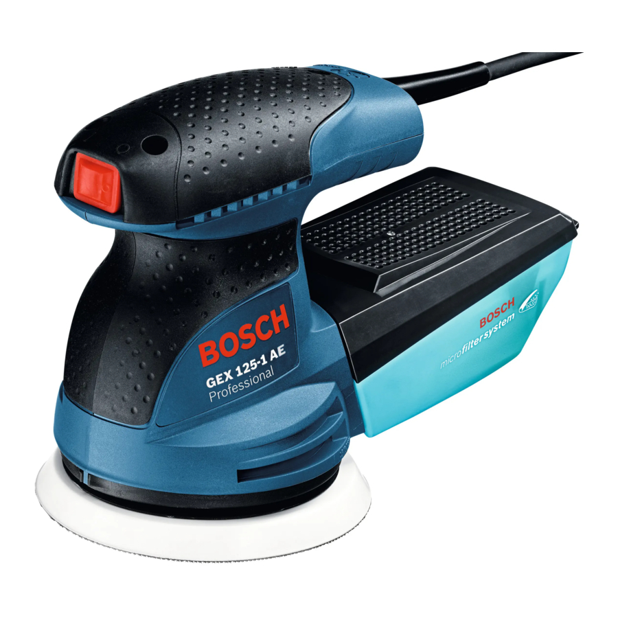
Product Features
The numbering of the product features refers to the diagram of the power tool on the graphics page.

- On/off switch
- Orbital stroke rate preselection thumbwheel (GEX 125-1 AE)
- Complete dust box (Microfilter system)
- Handle (insulated gripping surface)
- Sanding pad
- Sanding sheetA)
- Screws for sanding pad
- Extraction outlet
- Filter element (Microfilter system)
- Dust extraction hoseA)
A) Accessories shown or described are not included with the product as standard. You can find the complete selection of accessories in our accessories range.
Technical Data
| Random orbit sander | GEX 125-1 A | GEX 125-1 AE | |
| Article number | 3 601 C87 0.. | 3 601 C87 5.. | |
| Orbital stroke rate preselection | – | ● | |
| Rated power input | W | 250 | 250 |
| No-load speed n 0 | rpm | 12000 | 7500–12000 |
| No-load orbital stroke rate | rpm | 24,000 | 15,000–24,000 |
| Orbit diameter | mm | 2.5 | 2.5 |
| Sanding pad diameter | mm | 125 | 125 |
| Weight according to EPTA Procedure 01:2014 | kg | 1.3 | 1.3 |
| Protection class |  / II / II | / II |
Geräusch-/Vibrationsinformation
Noise emission values determined according to EN 62841-2-4.
Typically, the A-weighted sound pressure level of the power tool is 77 dB(A). Uncertainty K = 2.8 dB. The noise level when working can exceed 80 dB(A).
Wear hearing protection
Total vibration values ah (triax vector sum) and uncertainty K determined according to EN 62841-2-4:
ah = 5.0 m/s2, K = 1.5 m/s2,
The vibration level and noise emission value given in these instructions have been measured in accordance with a standardised measuring procedure detailed in EN 62841 and may be used to compare power tools. They may also be used for a preliminary estimation of vibration and noise emissions.
The given vibration level and noise emission value represent the main applications of the power tool. However, if the power tool is used for other applications, with different application tools or is poorly maintained, the vibration level and noise emission value may differ. This may significantly increase the vibration and noise emissions over the total working period.
To estimate vibration and noise emissions accurately, the times when the tool is switched off or when it is running but not actually being used should also be taken into account. This may significantly reduce vibration and noise emissions over the total working period.
Implement additional safety measures to protect the operator from the effects of vibration, such as servicing the power tool and application tools, keeping the hands warm, and organising workflows correctly.
Assembly
- Pull the plug out of the socket before carrying out any work on the power tool.
Selecting the Sanding Sheet
Different sanding sheets are available, depending on the material you are working with and the required surface removal rate:
| Material | Application | Grit | ||
 |
| For sanding down paint | Coarse | 40 60 |
| For sanding undercoats (e.g. removing brushstrokes, paint drips and paint runs) | Medium | 80 100 120 | ||
| For final sanding of primers prior to painting | Fine | 180 240 320 400 | ||
 | Expert for Wood
| For pre-sanding, e.g. of rough and uneven beams and boards | Coarse | 40 60 |
| For surface sanding and levelling of slight irregularities | Medium | 80 100 120 | ||
| For finish-sanding and fine sanding of wood | Fine | 180 240 320 400 | ||
 |
| For pre-sanding | Coarse | 80 |
| For shaping and edge chamfering | Medium | 100 120 | ||
| For fine sanding during shaping | Fine | 180 240 320 400 | ||
| Buffing and edge rounding | Very fine | 600 1200 |
Changing the sanding sheet (see figure A)

To remove the sanding sheet (6), lift it from the side and pull it from the sanding pad (5).
Remove dirt and dust from the sanding pad (5), e.g. with a paintbrush, before attaching a new sanding sheet.
The surface of the sanding pad (5) is fitted with a hook-andloop fastening, allowing sanding sheets with a similar backing to be secured quickly and easily.
Press the sanding sheet (6) firmly onto the underside of the sanding pad (5).
To ensure optimum dust extraction, make sure that the punched holes in the sanding sheet are aligned with the drilled holes in the sanding pad.

The alignment aid that is in the tool box and shown in the figure enables easy alignment of the sanding sheet (6) on the sanding pad (5). Place the sanding sheet into the alignment aid with the hook-and-loop fastening facing upwards and press the power tool with the sanding pad firmly onto it.
Selection of the Sanding Plate
The power tool can be fitted with sanding pads of various hardnesses, depending on the application:
- Extra soft sanding pad: Suitable for polishing and sensitive sanding, even on curved surfaces.
- Medium hard sanding pad: Suitable for all sanding work, universal application.
- Hard sanding pad: Suitable for heavy sanding on flat surfaces.
Changing the sanding pad (see figure B)

Note: Replace damaged sanding pads (5) immediately.
Remove the sanding sheet or polishing tool. Unscrew the four screws completely (7) and remove the sanding pad (5). Attach the new sanding pad (5) and retighten the screws.
Note: When attaching the sanding pad, make sure that the teeth of the catch mate with the recesses in the sanding pad.
Note: Damaged sanding pads must only be replaced by an after-sales service centre authorised to work with Bosch power tools.
Dust/chip extraction
The dust from materials such as lead paint, some types of wood, minerals and metal can be harmful to human health. Touching or breathing in this dust can trigger allergic reactions and/or cause respiratory illnesses in the user or in people in the near vicinity.
Certain dusts, such as oak or beech dust, are classified as carcinogenic, especially in conjunction with wood treatment additives (chromate, wood preservative). Materials containing asbestos may only be machined by specialists.
- Use a dust extraction system that is suitable for the material wherever possible.
- Provide good ventilation at the workplace.
- It is advisable to wear a P2 filter class breathing mask.
The regulations on the material being machined that apply in the country of use must be observed.
- Avoid dust accumulation at the workplace. Dust can easily ignite.
Self-generated dust extraction with dust box (see figure C1–C4)


Place the dust box (3) onto the extraction outlet (8) until it clicks into place.
You can easily check the filling level of the dust box (3) through the transparent container.
To empty the dust box (3), rotate and pull it downwards.
Before opening the dust box (3), knock the dust box against a firm surface as shown in the figure to loosen the dust from the filter element.
Holding the dust box (3) firmly, flap the filter element (9) upwards out of the way and empty the dust box. Use a soft brush to clean the flaps of the filter element (9).
External dust extraction (see figure D)

Fit a dust extraction hose (10) onto the extraction outlet (8). Connect the dust extraction hose (10) to an extractor. You will find an overview of connecting to various dust extractors at the beginning of these operating instructions.
The dust extractor must be suitable for the material being worked.
When extracting dry dust that is especially detrimental to health or carcinogenic, use a special dust extractor.
Operation
Starting Operation
- Pay attention to the mains voltage. The voltage of the power source must match the voltage specified on the rating plate of the power tool. Power tools marked 230 V can also be operated at 220 V.
- Products that are only sold in AUS and NZ: Use a residual current device (RCD) with a nominal residual current of 30 mA or less.
Switching On/Off
- Make sure that you are able to press the On/Off switch without releasing the handle.
To switch on the power tool, tilt the on/off switch (1) toward the right to the "I" position.
To switch off the power tool, tilt the on/off switch (1) toward the left to the "O" position.
Preselecting the orbital stroke rate (GEX 125-1 AE)
You can even preselect the orbital stroke rate during operation using the necessary orbital stroke rate preselection thumbwheel (2).
1–2 Low orbital stroke rate
3–4 Medium orbital stroke rate
5–6 High orbital stroke rate
The required orbital stroke rate is dependent on the material and the work conditions and can be determined using practical tests.
After working at a low orbital stoke rate for an extended period, you should operate the power tool at the maximum orbital stroke rate for approximately three minutes without load to cool it down.
Sanding Plate Brake
An integrated sanding pad brake reduces the orbital stroke rate when running without load to prevent scoring when the power tool is placed on the workpiece.
If the no-load orbital stroke rate constantly increases over time, this means that the sanding pad is damaged and must be replaced, or that the sanding pad brake is worn. A worn sanding pad brake must be replaced by an after-sales service centre authorised to work with Bosch power tools.
Working Advice
- Pull the plug out of the socket before carrying out any work on the power tool.
- Always wait until the power tool has come to a complete stop before placing it down.
- This power tool is not suitable for bench-mounted use. It must not be clamped into a vice or fastened to a workbench, for example.
For fatigue-free work, you can hold the power tool from above, from the side or from the front, depending on the application (see figure E).

Sanding Surfaces
Switch the power tool on, place the entire sanding surface against the surface of the workpiece and apply moderate pressure as you move the sander over the workpiece.
The material removal rate and sanding result are primarily determined by the choice of sanding sheet, the preselected orbital stroke rate level and the contact pressure.
Only immaculate sanding sheets achieve good sanding performance and make the power tool last longer. Be sure to apply consistent contact pressure in order to increase the lifetime of the sanding sheets.
Excessively increasing the contact pressure will not lead to increased sanding performance, rather it will cause more severe wear of the power tool and of the sanding sheet.
Do not use a sanding sheet for other materials after it has been used to work on metal.
Use only original Bosch sanding accessories.
Rough Sanding
Attach a coarse grit sanding sheet.
Apply only light pressure to the power tool so that it runs at a higher orbital stroke rate and a higher material removal rate is achieved.
Fine Sanding
Attach a fine grit sanding sheet.
You can reduce the sanding plate orbital stroke rate by lightly varying the contact pressure or changing the orbital stroke rate level; the random orbit motion will be retained. Move the power tool with moderate pressure flat on the workpiece in a circular motion or alternately along and across it. Do not tilt the power tool in order to avoid sanding through the workpiece, e.g. veneers.
Switch the power tool off after completing operation.
Polishing
For polishing weathered lacquers and redressing scratches (e.g. acrylic glass), the power tool can be fitted with an appropriate polishing tool, e.g. lambswool bonnet, polishing felt or polishing sponge (accessory).
Select a low orbital stroke rate (level 1–2) when polishing in order to avoid heating up the surface excessively.
Apply the polish to an area slightly smaller than the area which you intend to polish. Using the appropriate polishing tool, work in the polish with either linear or circular movements and with moderate pressure.
Do not allow the polish to dry out on the surface; this may damage the surface. Do not expose the surface which you intend to polish to direct sunlight.
Clean the polishing tool regularly to ensure good polishing results. Wash the polishing tools with mild detergent and warm water; do not use thinning agents.
Maintenance and Service
Maintenance and cleaning
- Pull the plug out of the socket before carrying out any work on the power tool.
- To ensure safe and efficient operation, always keep the power tool and the ventilation slots clean.
In order to avoid safety hazards, if the power supply cord needs to be replaced, this must be done by Bosch or by a customer service centre that is authorised to repair Bosch power tools.
After-sales service and advice on using products
Our after-sales service responds to your questions concerning maintenance and repair of your product as well as spare parts. You can find explosion drawings and information on spare parts at: www.bosch-pt.com
The Bosch product use advice team will be happy to help you with any questions about our products and their accessories.
In all correspondence and spare parts orders, please always include the 10‑digit article number given on the nameplate of the product.
Great Britain
Robert Bosch Ltd. (B.S.C.)
P.O. Box 98
Broadwater Park
North Orbital Road
Denham Uxbridge
UB 9 5HJ
At www.bosch-pt.co.uk you can order spare parts or arrange the collection of a product in need of servicing or repair.
Tel. Service: (0344) 7360109
E-Mail: boschservicecentre@bosch.com
Ireland
Origo Ltd.
Unit 23 Magna Drive
Magna Business Park
City West
Dublin 24
Tel. Service: (01) 4666700
Fax: (01) 4666888
Australia, New Zealand and Pacific Islands
Robert Bosch Australia Pty. Ltd.
Power Tools
Locked Bag 66
Clayton South VIC 3169
Customer Contact Center
Inside Australia:
Phone: (01300) 307044 Fax: (01300) 307045
Inside New Zealand:
Phone: (0800) 543353 Fax: (0800) 428570
Outside AU and NZ: Phone: +61 3 95415555
www.bosch-pt.com.au
www.bosch-pt.co.nz
Republic of South Africa
Customer service
Hotline: (011) 6519600
Gauteng – BSC Service Centre
35 Roper Street, New Centre
Johannesburg
Tel.: (011) 4939375
Fax: (011) 4930126
E-Mail: bsctools@icon.co.za
KZN – BSC Service Centre
Unit E, Almar Centre
143 Crompton Street
Pinetown
Tel.: (031) 7012120
Fax: (031) 7012446
E-Mail: bsc.dur@za.bosch.com
Western Cape – BSC Service Centre
Democracy Way, Prosperity Park
Milnerton
Tel.: (021) 5512577
Fax: (021) 5513223
E-Mail: bsc@zsd.co.za
Bosch Headquarters
Midrand, Gauteng
Tel.: (011) 6519600
Fax: (011) 6519880
E-Mail: rbsa-hq.pts@za.bosch.com
Documents / Resources
References
![www.bosch-pt.com]() Home | Bosch Power Tools
Home | Bosch Power Tools![www.bosch-pt.co.uk]() Home | Bosch Power Tools
Home | Bosch Power ToolsBosch power tools for trade and industry | Bosch Professional
Bosch power tools for trade and industry | Bosch Professional
Download manual
Here you can download full pdf version of manual, it may contain additional safety instructions, warranty information, FCC rules, etc.
Advertisement


Need help?
Do you have a question about the GEX Professional 125-1 A and is the answer not in the manual?
Questions and answers