DeWalt DCF809, DCF809M2T, DCF809P1, DCF809L2T, DCF809D1, DCF809D2T Manual
- Instructions manual (137 pages) ,
- Original instructions manual (68 pages) ,
- Instruction manual (41 pages)
Advertisement
- 1 Introduction
- 2 Technical Data
- 3 Residual Risks
- 4 Markings on Tool
- 5 ASSEMBLY AND ADJUSTMENTS
- 6 Included with some models
- 7 OPERATION
- 8 Forward/Reverse Control Button
- 9 USAGE
- 10 MAINTENANCE
- 11 Cleaning
- 12 Optional Accessories
- 13 Protecting the Environment
- 14 Definitions: Safety Guidelines
- 15 General Power Tool Safety Warnings
- 16 Additional Specific Safety Rules for Impact Drivers
- 17 Documents / Resources
Introduction
You have chosen a DeWALT tool. Years of experience, thorough product development and innovation make DeWALT one of the most reliable partners for professional power tool users. Technical Data
Technical Data
| DCF809 | ||
| Voltage | V DC | 18 |
| Type | 1/2 | |
| Battery type | Li-Ion | |
| No load speed min | min-1 | 0–2800 |
| Impact rate min | min-1 | 0–3200 |
| Max. torque | Nm | 190 |
| Tool holder | mm | 6.35 hex |
| Weight (without battery pack) | kg | 0.96 |
Noise values and/or vibration values (triax vector sum) according to EN62841-2-2:
| L PA (emission sound pressure level) | dB(A) | 91 |
| L WA (sound power level) | dB(A) | 99 |
| K (uncertainty for the given sound level) | dB(A) | 3 |
| Vibration emission value a h = | m/s 2 | 21 |
| Uncertainty K = | m/s 2 | 1.8 |
The vibration and/or noise emission level given in this information sheet has been measured in accordance with a standardised test given in EN62841 and may be used to compare one tool with another. It may be used for a preliminary assessment of exposure.

The declared vibration and/or noise emission level represents impact tightening of fasteners of the maximum capacity of the tool. However if the tool is used for different applications, with different accessories or poorly maintained, the vibration and/or noise emission may differ. This may significantly increase the exposure level over the total working period.
An estimation of the level of exposure to vibration and/or noise should also take into account the times when the tool is switched off or when it is running but not actually doing the job. This may significantly reduce the exposure level over the total working period.
Identify additional safety measures to protect the operator from the effects of vibration and/or noise such as: maintain the tool and the accessories, keep the hands warm (relevant for vibration), organisation of work patterns.
Residual Risks
In spite of the application of the relevant safety regulations and the implementation of safety devices, certain residual risks cannot be avoided. These are:
- Impairment of hearing.
- Risk of personal injury due to flying particles.
- Risk of burns due to accessories becoming hot during operation.
- Risk of personal injury due to prolonged use.
SAVE THESE INSTRUCTIONS
Battery Type
The DCF809 operates on an 18V volt battery pack.
These battery packs may be used: DCB181, DCB182, DCB183,
DCB183B, DCB183G, DCB184, DCB184B, DCB184G, DCB185, DCB187, DCB189, DCBP034, DCB546, DCB547, DCB548. Refer to Technical Data for more information.
Package Contents
The package contains:
1 Impact driver
1 Charger
1 Magnetic bit holder (included with some models)
1 Belt hook (included with some models)
1 Kitbox (included with some models)
1 Li-Ion battery pack (C1, D1, E1, G1, H1, L1, M1, P1, Q1, S1, T1, U1, X1, Y1, Z1 models)
2 Li-Ion battery packs (C2, D2, E2, G2, H2, L2, M2, P2, Q2, S2, T2, U2, X2, Y2, Z2 models)
3 Li-Ion battery packs (C3, D3, E3, G3, H3, L3, M3, P3, Q3, S3, T3, U3, X3, Y3, Z3 models)
- Check for damage to the tool, parts or accessories which may have occurred during transport.
- Take the time to thoroughly read and understand this manual prior to operation.
Markings on Tool
The following pictograms are shown on the tool:

Read instruction manual before use.
 Wear ear protection.
 Wear eye protection.
 Visible radiation. Do not stare into light.
Date Code Position
(Fig. A)
The date code 12 , which also includesthe year of manufacture, is printed into the housing.
Example:
2024 XX XX Year of Manufacture
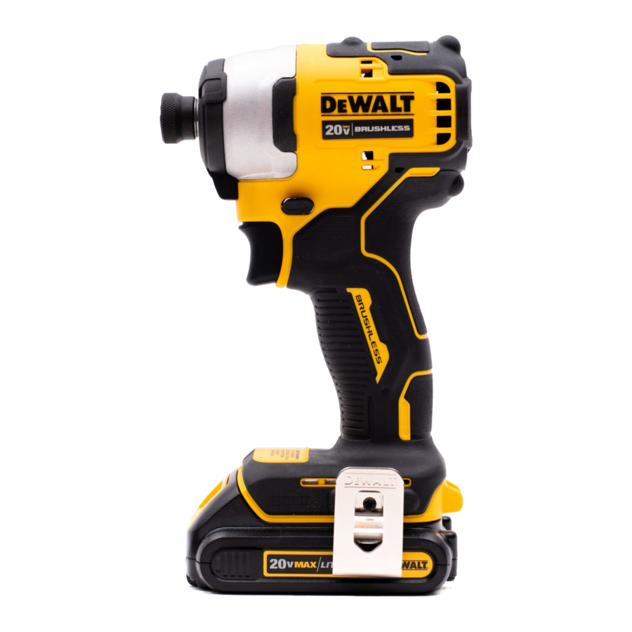
Description (Fig. A)

Never modify the power tool or any part of it.
Damage or personal injury could result.
- Battery pack
- Battery release button
- Variable speed trigger switch
- Forward/reverse control button
- Chuck collar
- 6.35 mm hex quick-release chuck
- Worklights
- Main handle
- Belt hook
- Screw
- Bit holder
- Date code
Intended Use
This impact driver is designed for professional impact screwdriving applications. The impact function makes this tool particularly useful for driving fasteners in wood, metal and concrete.
DO nOT use under wet conditions or in the presence of flammable liquids or gases.
This impact driver is a professional power tool.
DO nOT let children come into contact with the tool.
Supervision is required when inexperienced operators use this tool.
- Young children and the infirm. This appliance is not intended for use by young children or infirm persons without supervision.
- This product is not intended for use by persons (including children) suffering from diminished physical, sensory or mental abilities; lack of experience, knowledge or skills unless they are supervised by a person responsible for their safety. Children should never be left alone with this product.
ASSEMBLY AND ADJUSTMENTS
To reduce the risk of serious personal injury, turn tool off and disconnect battery pack before making any adjustments or removing/installing attachments or accessories. An accidental start-up can cause injury.
Use only DeWALT battery packs and chargers.
Inserting and Removing the Battery Pack from the Tool (Fig. A, B)
NOTE: Make sure your battery pack 1 is fully charged.
To Install the Battery Pack into the Tool Handle
- Align the battery pack 1 with the rails inside the tool's handle (Fig. B).

- Slide it into the handle until the battery pack is firmly seated in the tool and ensure that you hear the lock snap into place.

To Remove the Battery Pack from the Tool
- Press the release button 2 and firmly pull the battery pack out of the tool handle.
- Insert battery pack into the charger.
Fuel Gauge Battery Packs (Fig. A) Some DeWALT battery packs include a fuel gauge which consists of three green LED lights that indicate the level of charge remaining in the battery pack.
To actuate the fuel gauge, press and hold the fuel gauge button. A combination of the three green LED lights will illuminate designating the level of charge left. When the level of charge in the battery is below the usable limit, the fuel gauge will not illuminate and the battery will need to be recharged.
NOTE: The fuel gauge is only an indication of the charge left on the battery pack. It does not indicate tool functionality and is subject to variation based on product components, temperature and end-user application.
Belt Hook and Magnetic Bit Holder (Fig. A)
Included with some models
To reduce the risk of serious personal injury, DO NOT suspend tool overhead or suspend objects from the belt hook. ONLY hang tool's belt hook from a work belt.
To reduce the risk of serious personal injury, ensure the screw holding the belt hook is secure.

When attaching or replacing a belt hook or magnetic bit holder, use only the screw that is provided. Be sure to securely tighten the screw.
A belt hook 9 and magnetic bit holder 11 can be be attached to either side of the tool using only the screw 10 provided, to accommodate left- or right-handed users. If the hook or magnetic bit holder is not desired at all, it can be removed from the tool.
To move the belt hook or magnetic bit holder, remove the screw 10 that holds it in place then reassemble on the opposite side. Be sure to securely tighten the screw.
OPERATION
Instructions for Use
Always observe the safety instructions and applicable regulations.
To reduce the risk of serious personal injury, turn tool off and disconnect battery pack before making any adjustments or removing/installing attachments or accessories. An accidental start-up can cause injury.
Proper Hand Position (Fig. C)

To reduce the risk of serious personal injury, ALWAYS use proper hand position as shown. WARNING: To reduce the risk of serious personal injury, ALWAYS hold securely in anticipation of a sudden reaction.
Proper hand position requires one hand on the main handle 8 .
Variable Speed Trigger Switch (Fig. A, D)

To turn the tool on, squeeze the trigger switch 3 . To turn the tool off, release the trigger switch. Your tool is equipped with a brake. The chuck will stop when the trigger switch is fully released.
The variable speed switch enables you to start the application at a slow speed. The further you squeeze the trigger, the faster the tool will operate. For maximum tool life, use variable speed only for starting holes or fasteners.
nOTE: Continuous use in variable speed range is not recommended. It may damage the switch and should be avoided.
Forward/Reverse Control Button
(Fig. A, D)
A forward/reverse control button 4 determines the direction of the tool and also serves as a lock-off button.
To select forward rotation, release the trigger switch and depress the forward/reverse control button on the right side of the tool.
To select reverse, depress the forward/reverse control button on the left side of the tool. The centre position of the control button locks the tool in the off position. When changing the position of the control button, be sure the trigger is released.
nOTE: The first time the tool is run after changing the direction of rotation, you may hear a click on start up. This is normal and does not indicate a problem.
Worklights (Fig. A)
There are three worklights 7 located around the 6.35 mm hex chuck 6 . The worklights are activated when the trigger switch is depressed.
When the trigger is released, the worklight will stay illuminated for up to 20 seconds. If the trigger switch remains depressed, the worklights will remain on.
nOTE: The worklights are for lighting the immediate work surface and are not intended to be used as a flashlight.
Quick-Release Chuck (Fig. A, E, F)
Use only impact accessories. Non-impact accessories may break and cause a hazardous condition. Inspect accessory prior to use to ensure that it con tains no cracks.
nOTE: The chuck accepts 6.35 mm hex bit tips only. Using 25 mm bits allows better access in tight spaces.
Place the forward/reverse button 4 in the locked off (centre) position or remove battery pack before changing accessories.
To install an accessory (Fig. E), push accessory to fully insert into chuck 6 . The chuck collar 5 does not need to be pulled up to lock accessory in place.

To remove an accessory (Fig. F), pull the chuck collar away from the front of the tool. Remove the accessory and release the collar.

USAGE
Your impact tool generates the following maximum torque:
| Cat # | Nm | Ft.-Lbs. | In.-Lbs |
| DCF809 | 190 | 142 | 1700 |

Ensure fastener and/or system will withstand the level of torque generated by the tool. Excessive torque may cause breakage and possible personal injury.
- Place the accessory on the fastener head. Keep the tool pointed straight at the fastener.
- Press switch to start operation. Release the switch to stop operation. Always check torque with a torque wrench, as the fastening torque is affected by many factors including the following:
- Voltage: Low voltage, due to a nearly discharged battery, will reduce fastening torque.
- Accessory size: Failure to use the correct accessory size will cause a reduction in fastening torque.
- Bolt Size: Larger bolt diameters generally require higher fastening torque. Fastening torque will also vary according to length, grade, and torque coefficient.
- Bolt: Ensure that all threads are free of rust and other debris to allow proper fastening torque.
- Material: The type of material and surface finish of the material will affect fastening torque.
- Fastening time: Longer fasten ing time results in increased fastening torque. Using a longer fastening time than recommended could cause the fasteners to be overstressed, stripped or damaged.
MAINTENANCE
Your DeWALT power tool has been designed to operate over a long period of time with a minimum of maintenance. Continuous satisfactory operation depends upon proper tool care and regular cleaning.
To reduce the risk of serious personal injury, turn tool off and disconnect battery pack before making any adjustments or removing/installing attachments or accessories. An accidental start-up can cause injury. The charger and battery pack are not serviceable.
Lubrication
Your power tool requires no additional lubrication.
Cleaning
Blow dirt and dust out of the main housing with dry air as often as dirt is seen collecting in and around the air vents. Wear approved eye protection and approved dust mask when performing this procedure.
Never use solvents or other harsh chemicals for cleaning the non-metallic parts of the tool. These chemicals may weaken the materials used in these parts. Use a cloth dampened only with water and mild soap. Never let any liquid get inside the tool; never immerse any part of the tool into a liquid.
Optional Accessories
Since accessories, other than those offered by DeWALT, have not been tested with this product, use of such accessories with this tool could be hazardous. To reduce the risk of injury, only DeWALT recommended accessories should be used with this product.
Use only impact accessories. Non-impact accessories may break and cause a hazardous condition. Inspect accessories prior to use to ensure that they contain no cracks. Consult your dealer for further information on the appropriate accessories.
Protecting the Environment


Products/batteries are recyclable, but if marked with the crossed-out bin, they must not be disposed of with normal household waste.
Run the batteries down completely and separate them, and separate any light sources from the product if possible. It is the user's responsibility to delete personal data from the product. Then take the waste to an official waste collection center or a participating retailer who will often accept it free of charge. Packaging should be discarded based on the marked material code. Operating and safety instructions should only be discarded once the applicable product is no longer in use. Please check with your local community/municipality for waste management guidance. For further information, visit www.2helpU.com and scan the above QR code.
Definitions: Safety Guidelines
The definitions below describe the level of severity for each signal word. Please read the manual and pay attention to these symbols.

Indicates an imminently hazardous situation which, if not avoided, will result in death or serious injury.
Indicates a potentially hazardous situation which, if not avoided, could result in death or serious injury.
Indicates a potentially hazardous situation which, if not avoided, may result in minor or moderate injury.
NOTICE: Indicates a practice not related to personal injury which, if not avoided, may result in property damage.
 Denotes risk of electric shock.
 Denotes risk of fire.
General Power Tool Safety Warnings
Read all safety warnings, instructions, illustrations and specifications provided with this power tool. Failure to follow all instructions listed below may result in electric shock, fire and/or serious injury.
SAVE ALL WARNINGS AND INSTRUCTIONS FOR FUTURE REFERENCE.

*Date code 201811475B or later
**Date code 201536 or later
***Battery charge times matrix provided for guidance only; charge times will vary depending on temperature and condition of batteries.
The term "power tool" in the warnings refers to your mainsoperated (corded) power tool or battery-operated (cordless) power tool.
Work Area Safety
- Keep work area clean and well lit. Cluttered or dark areas invite accidents.
- Do not operate power tools in explosive atmospheres, such as in the presence of flammable liquids, gases or dust. Power tools create sparks which may ignite the dust or fumes.
- Keep children and bystanders away while operating a power tool. Distractions can cause you to lose control.
Electrical Safety
- Power tool plugs must match the outlet. Never modify the plug in any way. Do not use any adapter plugs with earthed (grounded) power tools. Unmodified plugs and matching outlets will reduce risk of electric shock.
- Avoid body contact with earthed or grounded surfaces such as pipes, radiators, ranges and refrigerators. There is an increased risk of electric shock if your body is earthed or grounded.
- Do not expose power tools to rain or wet conditions.
Water entering a power tool will increase the risk of electric shock. - Do not abuse the cord. Never use the cord for carrying, pulling or unplugging the power tool. Keep cord away from heat, oil, sharp edges or moving parts. Damaged or entangled cords increase the risk of electric shock.
- When operating a power tool outdoors, use an extension cord suitable for outdoor use. Use of a cord suitable for outdoor use reduces the risk of electric shock.
- If operating a power tool in a damp location is unavoidable, use a residual current device (RCD) protected supply. Use of an RCD reduces the risk of electric shock.
Personal Safety
- Stay alert, watch what you are doing and use common sense when operating a power tool. Do not use a power tool while you are tired or under the influence of drugs, alcohol or medication. A moment of inattention while operating power tools may result in serious personal injury.
- Use personal protective equipment. Always wear eye protection. Protective equipment such as dust mask, non-skid safety shoes, hard hat or hearing protection used for appropriate conditions will reduce personal injuries.
- Prevent unintentional starting. Ensure the switch is in the off-position before connecting to power source and/or battery pack, picking up or carrying the tool. Carrying power tools with your finger on the switch or energising power tools that have the switch on invites accidents.
- Remove any adjusting key or wrench before turning the power tool on. A wrench or a key left attached to a rotating part of the power tool may result in personal injury.
- Do not overreach. Keep proper footing and balance at all times. This enables better control of the power tool in unexpected situations.
- Dress properly. Do not wear loose clothing or jewellery.
Keep your hair and clothing away from moving parts. Loose clothes, jewellery or long hair can be caught in moving parts. - If devices are provided for the connection of dust extraction and collection facilities, ensure these are connected and properly used. Use of dust collection can reduce dust-related hazards.
- Do not let familiarity gained from frequent use of tools allow you to become complacent and ignore tool safety principles. A careless action can cause severe injury within a fraction of a second.
Power Tool Use and Care
- Do not force the power tool. Use the correct power tool for your application. The correct power tool will do the job better and safer at the rate for which it was designed.
- Do not use the power tool if the switch does not turn it on and off. Any power tool that cannot be controlled with the switch is dangerous and must be repaired.
- Disconnect the plug from the power source and/or remove the battery pack, if detachable, from the power tool before making any adjustments, changing accessories, or storing power tools. Such preventive safety measures reduce the risk of starting the power tool accidentally.
- Store idle power tools out of the reach of children and do not allow persons unfamiliar with the power tool or these instructions to operate the power tool. Power tools are dangerous in the hands of untrained users.
- Maintain power tools and accesories. Check for misalignment or binding of moving parts, breakage of parts and any other condition that may affect the power tool's operation. If damaged, have the power tool repaired before use. Many accidents are caused by poorly maintained power tools.
- Keep cutting tools sharp and clean. Properly maintained cutting tools with sharp cutting edges are less likely to bind and are easier to control.
- Use the power tool, accessories and tool bits, etc. in accordance with these instructions, taking into account the working conditions and the work to be performed. Use of the power tool for operations different from those intended could result in a hazardous situation.
- Keep handles and grasping surfaces dry, clean and free from oil and grease. Slippery handles and grasping surfaces do not allow for safe handling and control of the tool in unexpected situations.
Battery Tool Use and Care
- Recharge only with the charger specified by the manufacturer. A charger that is suitable for one type of battery pack may create a risk of fire when used with another battery pack.
- Use power tools only with specifically designated battery packs. Use of any other battery packs may create a risk of injury and fire.
- When battery pack is not in use, keep it away from other metal objects, like paper clips, coins, keys, nails, screws or other small metal objects, that can make a connection from one terminal to another. Shorting the battery terminals together may cause burns or a fire.
- Under abusive conditions, liquid may be ejected from the battery; avoid contact. If contact accidentally occurs, flush with water. If liquid contacts eyes, additionally seek medical help. Liquid ejected from the battery may cause irritation or burns.
- Do not use a battery pack or tool that is damaged or modified. Damaged or modified batteries may exhibit unpredictable behaviour resulting in fire, explosion or risk of injury.
- Do not expose a battery pack or tool to fire or excessive temperature. Exposure to fire or temperature above 130°C may cause explosion.
- Follow all charging instructions and do not charge the battery pack or tool outside the temperature range specified in the instructions. Charging improperly or at temperatures outside the specified range may damage the battery and increase the risk of fire.
Service
- Have your power tool serviced by a qualified repair person using only identical replacement parts. This will ensure that the safety of the power tool is maintained.
- Never service damaged battery packs. Service of battery packs should only be performed by the manufacturer or authorized service providers.
Additional Specific Safety Rules for Impact Drivers
- Hold the power tool by insulated gripping surfaces when performing an operation where the fastener may contact hidden wiring. Fasteners contacting a "live" wire may make exposed metal parts of the power tool "live" and could give the operator an electric shock.
- Wear ear protectors during use. Exposure to noise can cause hearing loss.
![]()
Impact wrenches are not torque wrenches. DO NOT use this tool for tightening fasteners to specified torques. An independent, calibrated torque measurement device such as a torque wrench should be used when under-tightened or overtightened fasteners can lead to the failure of the joint.
Documents / Resources
References

Download manual
Here you can download full pdf version of manual, it may contain additional safety instructions, warranty information, FCC rules, etc.
Download DeWalt DCF809, DCF809M2T, DCF809P1, DCF809L2T, DCF809D1, DCF809D2T Manual
Advertisement


Need help?
Do you have a question about the DCF809 and is the answer not in the manual?
Questions and answers