ABB ACS580 Manual
- Hardware manual (468 pages) ,
- Firmware manual (440 pages) ,
- Quick start manual (116 pages)
Advertisement
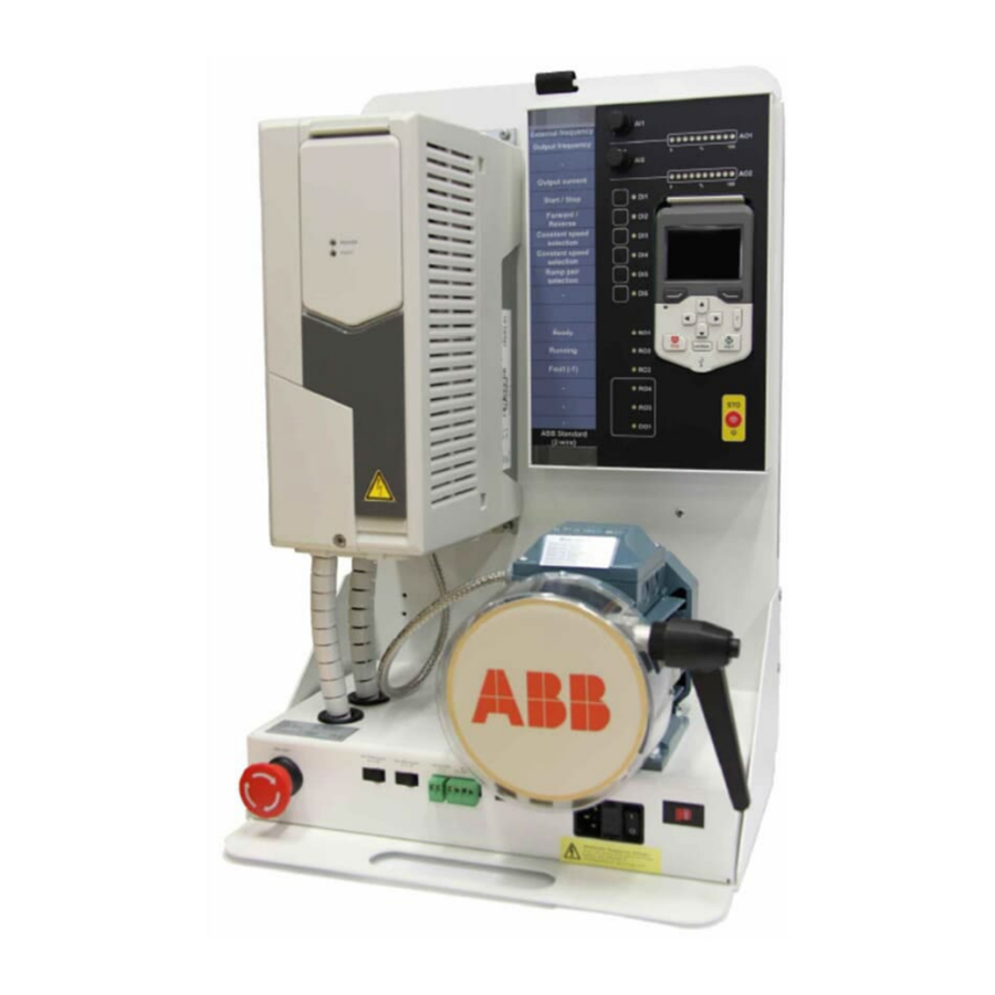
Delivery content
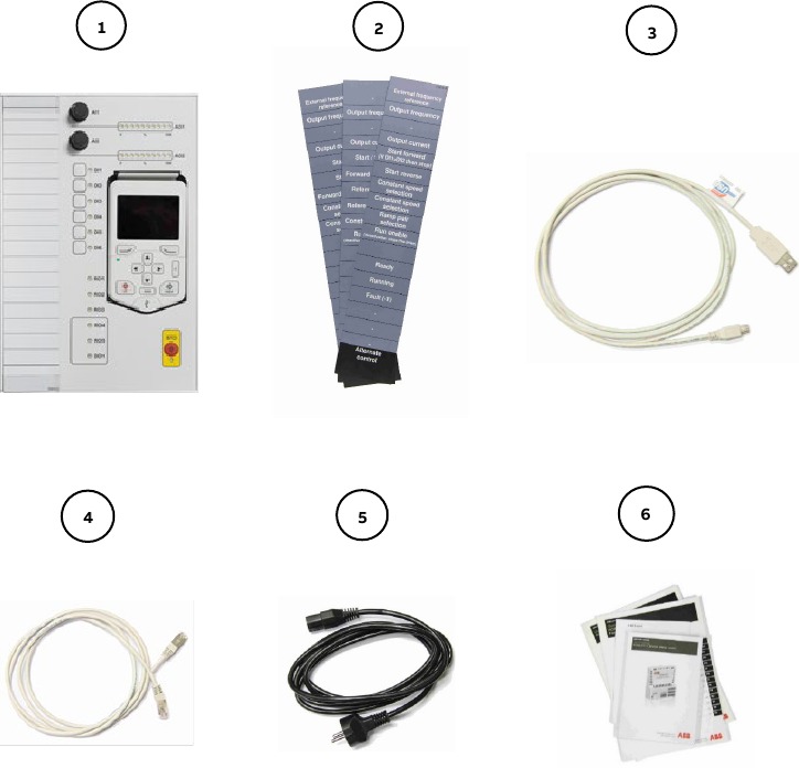
ACS580 democase contains: (found in the pocket at the back of the democase)
- I/O-panel with removable control panel
- External control mode cards
- USB to Mini USB – cable for PC-connection
- Ethernet cable for I/O-panel connection (CAT5E UTP, unshielded)
- Mains cord (also US cord included)
- Set of manuals including:
- ACS580-01 Hardware manual
- ACS580 control program firmware manual
- ACS580-01 quick installation and start-up guide
- CDPI-01 communication adapter module installation guide
- CMOD-01 multi-function extension module user's manual
 NOTE: Ethernet adapter is not included in the democase delivery.
Layout

Supply switches
The demo supply can be controlled with the 24VDC external power supply switch and drive main supply switch. The two switches work separately. The 24VDC supply switch controls the external 24VDC supply to the control unit of the drive and the drive main supply switch controls the 400V main supply to the drive.
For information about the internal connections refer to Technical data section.
Replacing the fuses

Turn off the democase and disconnect the power cord before changing the fuse. Replace the fuse with the same type of fuse.
Replacing the fuse does not require any tools. Open the fuse terminal by pressing together the pins on the top and bottom of the fuse terminal and pulling the terminal out. Pull out the old fuses and replace them with new fuses of the same type. Push the fuse terminal back in.
Correct fuse type is: T2AL250V (Slow, 2.0A, 250V glass tube fuse) There are two fuses of this type in the fuse terminal.

Basic start-up
- Put the democase on its back (so that the cover is pointing up) and open the cover. Open the democase by releasing three metal hatches on the sides of the case.

- Pull the demo out of the case using the lifting strap and the handle hole (on the lower part of the demo.)
![]()
The demo weighs approximately 18 kg (40 lb). Use a proper lifting technique with a straight back.

- Take out the mains cord and Ethernet cable from the pocket at the back of the demo.

- Plug in the mains cord to connections marked: mains cord.
Make sure that the input voltage switch (115V/230V) is set according to the supply voltage. For more information refer to "AC input (supply) connection" in the Technical data section.

Mains cord connection and input voltage switch are located on the right side of the demo unit. - Plug in the Ethernet cable for I/O-panel to connections marked: I/O-panel connection A and I/O-panel connection B on the layout section.
![warning]() Note: The communication is serial communication and the cable must be point-to-point from connections A to B. No daisy-chain or bus topology cabling allowed.
Note: The communication is serial communication and the cable must be point-to-point from connections A to B. No daisy-chain or bus topology cabling allowed.

I/O-panel connection A is located next to mains cord connection and the I/O-panel connection B is located at the bottom of the I/O-panel as shown in the pictures above. - Switch on the demo using the mains switch.

- You can toggle control between the control panel and the IO-panel with the "Loc/Rem" –button on the control panel.
- Make sure from "Menu" – "System info" that the drive and control panel firmware versions are up to date. The latest firmware versions can be ABB's IHMM.
![warning]() Note: When you shut down the demo first turn off the power switch.
Note: When you shut down the demo first turn off the power switch.


Mechanical brake
The mechanical brake is intended for momentary impulse braking for load demonstration purposes. The mechanical brake is not designed for continuous load which might damage the transformer and the brake itself.
Commissioning
First start assistant
To commission the drive, step through the First start assistant. Note that the nominal values must be set according to the type label of the motor. In case of a problem, the instructions for First start assistant can be found in the ACS580-01 quick installation and start-up guide delivered with the democase. The nominal values of the motor are presented in the rightmost column in the table.
The First start assistant does not occur
If the drive has already been commissioned (i.e. First start assistant does not occur when switching on the demo) check that the motor nameplate parameters are set according the motor. The parameters can be checked from Parameters → modified. First start assistant can also be redone from Primary settings → Advanced functions → First start assistant.
Nominal values are correct, but the drive does not function properly
In case the nominal values are correct, and the drive does not function as desired, one can always restore the factory settings from
Primary settings → Reset defaults → Reset all to factory defaults
After this, the drive will start the First start assistant from the beginning.
Default I/O-panel functions

Floating point control / Motor potentiometer
Demo I/O-panel buttons DI1 to DI6 are possible to use two ways: toggle function and pulse function.
A cycle press shorter than 2 seconds changes the state of Digital Input permanently (toggle feature).
A cycle press longer than 2 seconds releases the state of Digital Input after button is released (pulse feature).
LED will indicate the actual status of Digital Input.

Panel bus
One ACS-AP-x control panel can be connected to up to 32 drives. Before beginning make sure that every drive is assigned with a unique drive id in the parameter number 49.01.
Use standard Ethernet cable for daisy chaining the democases to a single control panel. (Cables are not delivered with a democase).
- Make sure that the I/O panel is connected to democase using Ethernet –type (CAT5e) cable between connection A and connection B.
- Remove the control panels from I/O-panels of all democases.
- Connect master control panel to the leftmost connector of the I/O panel of the first drive using Ethernet cable
![warning]() Note: The connection is EIA-485 serial communication.
Note: The connection is EIA-485 serial communication.- The RJ45 connector is located on top inner side of the control panel mounting slot (see photo below).
- Connect second and further Ethernet type (CAT5e) cables between panel mounting slots of the I/O panels.

CDPI-01 must be connected to the panel slot of the drive in order for the panel bus to work.

Technical data
Dimensions of the democase
Height: 650 mm / 25.6 in
980 mm / 38.6 in (trolley handle pulled up) Width: 490 mm / 19.3 in
Depth: 385 mm / 15.2 in
Weight: 27 kg / 60 lb
Dimensions of the demo
- Height: 552 mm / 21.7 in
- Width: 357 mm / 14.1 in
- Depth: 282 mm / 11.1 in
- Weight: 18 kg / 40 lb
Drive type code
ACS580-01-02A7-4+J429+K475+L501+R700
(J429 = ACS-AP-W, K475 = FENA-21, L501 = CMOD-01, R700 = English manuals)
Motor details
Motor type code: ABB M2VA 63 B 4 (3GVA 062 142-ASC)
Motor nameplate:
| Parameter | ACS580 parameter | Value |
| Motor type | 99.03 Motor type | AM |
| Rated current In | 99.06 Motor nominal current | 1.2 A |
| Rated voltage Un | 99.07 Motor nominal voltage | 230.0 V |
| Frequency Fn | 99.08 Motor nominal frequency | 50.0 Hz |
| Rated speed | 99.09 Motor nominal speed | 1360 rpm |
| Rated power Pn | 99.10 Motor nominal power | 0.18 kW |
| COS φ | 99.11 Motor nominal cosfii | 0.71 |
| Rated torque | 99.12 Motor nominal torque | 0.82 Nm |
AC input (supply) connection
U1 ~ 115VAC or 230VAC (L, N, PE)
The democase can be used with both 115V and 230V supply. It is important to make sure that the input voltage switch (115V/230V) is in the correct position for the supply. For example, if you are using 230V supply, then "230V" should be visible in the switch. If the switch is set incorrectly, you will burn the fuse.
Degree of protection
Drive: IP21
Motor: IP55
Complete demo: IP20
Ambient conditions
The demo is designed for demonstration purposes and for indoor use only.
Ambient temperature:
- Transport: -40 to +70°C
- Storage: -40 to +70°C
- Operation: -15 to +40°C, no frost allowed
Altitude:
- 0 to 4,000 m without an effect on demo operation
Relative humidity:
- 5 to 95%, no condensation allowed.
For more detailed information, refer to the drive Hardware Manual.
The Safe torque off function
This chapter describes the Safe torque off (STO) function of the drive and gives instructions for its use.
Description
The Safe torque off function can be used, for example, as the final actuator device of safety circuits (such as an emergency stop circuit) that stop the drive in case of danger. Another typical application is a prevention of unexpected start-up function that enables short-time maintenance operations like cleaning or work on non-electrical parts of the machinery without switching off the power supply to the drive.
Note: The Safe torque off function does not disconnect the voltage from the drive.
When activated, the Safe torque off function disables the control voltage for the power semiconductors of the drive output stage, thus preventing the drive from generating the torque required to rotate the motor. If the motor is running when Safe torque off is activated, it coasts to a stop.
The Safe torque off function has a redundant architecture, that is, both channels must be used in the safety function implementation. The safety data given in this manual is calculated for redundant use, and does not apply if both channels are not used.
Compliance
The Safe torque off function of the drive complies with these standards:
| Standard | Name |
| EN 60204-1:2006 + AC:2010 | Safety of machinery – Electrical equipment of machines – Part 1: General requirements |
| IEC 61326-3-1:2008 | Electrical equipment for measurement, control and laboratory use – EMC requirements – Part 3-1: Immunity requirements for safety related systems and for equipment intended to perform safety related functions (functional safety) – General industrial applications |
| IEC 61508-1:2010 | Functional safety of electrical/electronic/programmable electronic safety-related systems – Part 1: General requirements |
| IEC 61508-2:2010 | Functional safety of electrical/electronic/programmable electronic safety-related systems – Part 2: Requirements for electrical/electronic/ programmable electronic safety-related systems |
| IEC 61511:2003 | Functional safety – Safety instrumented systems for the process industry sector |
| IEC/EN 61800-5-2:2007 | Adjustable speed electrical power drive systems – Part 5-2: Safety requirements – Functional |
| IEC/EN 62061:2005 + A1:2013 | Safety of machinery – Functional safety of safetyrelated electrical, electronic and programmable electronic control systems |
| EN ISO 13849-1:2008 + AC:2009 | Safety of machinery – Safety-related parts of control systems – Part 1: General principles for design |
| EN ISO 13849-2:2012 | Safety of machinery – Safety-related parts of control systems – Part 2: Validation |
The function also corresponds to Prevention of unexpected start-up as specified by
EN 1037:1995 + A1:2008 and Uncontrolled stop (stop category 0) as specified in EN 60204-1:2006 + AC:2010.
Validation test procedure
After wiring the Safe torque off function, validate its operation as follows.
| Action | □ |
 Obey the safety instructions. If you ignore them, injury or death, or damage to the equipment can occur. | □ |
| Ensure that the drive can be run and stopped freely during start-up. | □ |
| Stop the drive (if running), switch the input power off and isolate the drive from the power line by a disconnector. | □ |
| Check the Safe torque off circuit connections against the wiring diagram. | □ |
| Switch the power on. | □ |
Test the operation of the STO function when the motor is stopped.
| □ |
Ensure that the drive operates as follows:
| □ |
Test the operation of the STO function when the motor is running.
| □ |
| Document and sign the acceptance test report which verifies that the safety function is safe and accepted for operation. | □ |
STO Maintenance
After the operation of the circuit is validated at start-up, the STO function shall be maintained by periodic proof testing. In high demand mode of operation, the maximum proof test interval is 20 years. In low demand mode of operation, the maximum proof test interval is 10 years. The test procedure is given in section Validation test procedure.
In addition to proof testing, it is a good practice to check the operation of the function when other maintenance procedures are carried out on the machinery.
Include the Safe torque off operation test described above in the routine maintenance program of the machinery that the drive runs.
If any wiring or component change is needed after start up, or the parameters are restored, follow the test given in section Validation test procedure.
Use only spare part approved by ABB.
Any failures of the Safe torque off function must be reported to ABB.
Troubleshooting and maintenance
Internal connections

Control board wiring


Further information
Product and service inquiries
Address any inquiries about the product to your local ABB representative, quoting the type designation and serial number of the unit in question. A listing of ABB sales, support and service contacts can be found by navigating to www.abb.com/searchchannels.
Product training
For information on ABB product training, navigate to new.abb.com/service/training.
Providing feedback on ABB manuals
Your comments on our manuals are welcome. Navigate to new.abb.com/drives/manuals-feedback-form.
Safety instructions
General safety instructions
These safety instructions are intended for all personnel who work on the drive. For complete safety instructions, see the drive hardware manuals.
Obey these instructions. If you ignore them, injury or death, or damage to the equipment can occur. If you are not a qualified electrical professional, do not do installation or maintenance work.
- Make sure that the drive and all adjoining equipment are properly grounded.
- Do not do any maintenance on powered drive.
- After disconnecting the input power, always wait for 5 minutes to let the intermediate circuit capacitors discharge before you start working on the drive, motor or motor cable.
- Measure that the installation is de-energized. Use a quality voltage tester. Before and after you measure the installation, verify the operation of the voltage tester on a known voltage source.
If the demo unit is operated within the transportation enclosure, note that the motors and drives have less air available for cooling, which may result in overheating.
The democase is intended for demo purposes only. Using democase as a part of any process or application other than the intended demo use is strictly prohibited. Never remove the cover of the motor shaft or connect a load to it.
The democase (demo drive inside transportation case) is a heavy item, see the weights in the Technical data section. Follow the lifting instructions found inside the democase. Lifting the democase requires two persons. Do not lift the democase alone!
General guidelines for safe lifting
- Get as close to the load as possible.
- Keep your elbows and arms close to your body.
- Keep your back straight during the lift by tightening the stomach muscles, bending at the knees, keeping the load close and centered in front of you, and looking up and ahead.
- Get a good grip and do not twist while lifting.
- Do not jerk; use a smooth motion while lifting.
- If the load is too heavy to allow this, find someone to help you with the lift.
- Do not lift more than 25 kg or 50 pounds.
Safe torque off connection
The STO (safe torque off) button on the I/O-panel is meant for demo purposes only and is not directly part of the STO circuitry. The states of the I/O panel buttons are transmitted through the I/O cable in serial form and transferred to actual I/O states inside the democase. This has the consequence that missing the I/O cable doesn't cause STO to activate.
Documents / Resources
References
Download manual
Here you can download full pdf version of manual, it may contain additional safety instructions, warranty information, FCC rules, etc.
Advertisement


Need help?
Do you have a question about the ACS580 and is the answer not in the manual?
Questions and answers