Advertisement
Receiving and Inspection
Carefully inspect the fan and accessories for any damage and shortage immediately upon receipt of the fan.
- Turn the propeller by hand to ensure it turns freely and does not bind.
- Record on the Delivery Receipt any visible sign of damage.
Handling
Handle your equipment with care. Some fans are provided with lifting lugs or eyes for easy handling. Others must be handled using nylon straps or well-padded chains and cables which protect the fan's coating and housing. SPreader bars should be used when lifting large parts.
Axial fans should not be lifted by using straps around the fan housing only.
NOTICE! Never lift by the motor, motor base, propeller or flanges.
Storage
If the fan is stored for any length of time prior to installation, completely fill the bearings with grease or moisture inhibiting oil (refer to Lubrication).Store the fan in its original crate and protect it from dust, debris and weather.
Outdoor Storage
To maintain good working condition of a Vane Axial fan when it is stored outdoors or on a construction site, follow the additional steps below.
- Cover the inlet and outlet and belt tunnel opening to prevent the accumulation of dirt and moisture in the housing.
- Periodically rotate the prop and operate dampers (if supplied) to keep a coating of grease on all internal bearing parts.
- Periodically inspect the unit to prevent damaging conditions.
Installation
To prevent damage to the fan during shipping, motors 25 HP and larger and extremely heavy motors (cast iron or severe duty) are shipped loose and must be field mounted by bolting the motor on the motor mounting plate in the existing mounting slots.
 NOTICE! Extreme vibration is a serious problem that may cause structural and mechanical failure. To help vibration and noise from being transferred to the building, isolators are recommended.
Isolation Installation
Floor Mounted Spring Isolators

- Mount fan and motor on unitary base (if supplied).
- Elevate fan (or isolation base) to operating height and insert blocks to hold in position.
- Position isolators under the fan and vertically align by inserting leveling bolt through mounting holes in the fan or the base. The isolator must be installed on a level surface.
- Adjust the isolators by turning the leveling nut counterclockwise several turns at a time alternately on each isolator until the fan weight is transferred onto the isolators and the fan raises uniformly off the blocks. Then remove the blocks.
- Turn lock nut onto leveling bolt and secure firmly in place against the top of the mounting flange or frame.
- Secure isolators to mounting surface.
Floor Mounted Rubber-In-Shear (RIS) Isolators
- Mount fan and motor on a unitary isolation base (if supplied).
- Elevate fan to provide room to insert isolators between the fan and foundation and block in position.
- Position isolators under fan and secure bolts.
- Remove blocks and allow fan to rest on floor. Isolators must be installed on a level surface (leveling should not be required).
- Secure isolators to mounting surface.
Ceiling Mounted Spring and Rubber-in-Shear (RIS) Isolators

- Elevate fan to operating height and brace.
- Attach threaded rod to overhead support structure directly above each mounting hole. Rod should extend to within a few feet of fan.
- Attach isolator to end of threaded rod using a nut on each side of isolator bracket.
- Insert another section of threaded rod through the fan mounting hole and isolator.
- Attach two nuts to threaded rod in isolator.
- Place adjusting nut and locking nut on threaded rod near fan mounting bracket.
- Alternately rotate adjusting nut at each mounting location until the fan weight is uniformly transferred to the isolators. Remove bracing.
Duct Installation
Efficient fan performance relies on the proper installation of inlet and discharge ducts. Be sure your fan conforms to the following guidelines.
Non-Ducted Inlet Clearance
If your fan has an open inlet (no duct work), the fan must be placed one fan wheel diameter away from walls and bulkheads.

Free Discharge
Avoid a free discharge into the plenum. This will result in lost efficiency because it doesn't allow for a static regain.

Inlet Duct Turns
For ducted inlets, allow at least three fan wheel diameters between duct turns or elbows and the fan inlet.

Discharge Duct Turns
When possible, allow three duct diameters between duct turns or elbows and the fan outlet.

Belt and Pulley Installation
Belt tension is determined by the sound the belts make when the fan is first started. The belts will produce a loud squeal, which dissipates after the fan is operating at full capacity. If belt tension is too tight or too loose, lost efficiency and damage can occur.
Do not change the pulley pitch diameter to change tension. This will result in a different fan speed.
- Loosen motor plate adjustment bolts and move motor plate in order that the belts can easily slip into grooves on pulleys. Never pry, roll or force the belts over the rim of the pulley.
- Slide motor plate back until proper tension is reached. For proper tension, a deflection of approximately 1/4" per foot of center distance should be obtained by firmly pressing the belt.
![]()
- Lock the motor plate adjustment nuts in place.
- Ensure pulleys are properly aligned.
![]()
Tolerance
Center Distance Max. Gap Up through 12" 1/16" 12" up through 48" 1/8" Over 48" 1/4"

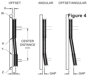
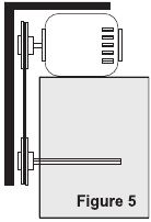
Pulley Alignment
Pulley alignment is adjusted by loosening the motor pulley setscrew and by moving the motor pulley on the motor shaft.
Figure 4 indicates where to measure the allowable gap for the drive alignment tolerance. All contact points (indicated by WXYZ) are to have a gap less than the tolerance shown in the table. When the pulleys are not the same width, the allowable gap must be adjusted by half of the difference in width (as shown in A & B of Figure 4). Figure 5 illustrates using a carpenter's square to adjust the position of the motor pulley until the belt is parallel to the longer leg of the square.
Wiring Installation
Leave enough slack in the wiring to allow for motor movement when adjusting belt tension. Some fractional motors have to be removed in order to make the connection with the terminal box at the end of the motor. To remove motor, remove bolts securing motor base to power assembly. Do not remove motor mounting bolts.
NOTICE! Follow the wiring diagram in the disconnect switch and the wiring diagram provided with the motor. Correctly label the circuit on the main power box and always identify a closed switch to promote safety (i.e., red tape over a closed switch).
Use of Variable Frequency Drives
Motors
Motors that are to be operated using a Variable Frequency Drive (VFD) must be VFD compatible. At a minimum, this must be a Premium Efficiency motor with Class F insulation. Motors that are not supplied by Loren Cook Company should have the recommendation of the motor manufacturer for use with a VFD.
Grounding
The fan frame, motor and VFD must be connected to a common earth ground to prevent transient voltages from damaging rotating elements.
Wiring
Line reactors may be required to reduce over-voltage spikes in the motors. The motor manufacturer should be consulted for recommended line impedance and usage of line reactors or filters if the lead length between the VFD and the motor exceeds 10 ft (3m).
Fan
It is the responsibility of the installing body to perform coast-down tests and identify any resonant frequencies after the equipment is fully installed. These resonant frequencies are to be removed from the operating range of the fan by using the "skip frequency" function in the VFD programming. Failure to remove resonant frequencies from the operating range will decrease the operating life of the fan and void the warranty.
Please refer to AVA Critical Fan Speed. Variable frequency drives should not allow AVA fans to operate between the low and the high speeds list.
Wiring Diagrams
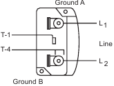
Single Speed, Single Phase Motor
When ground is required, attach to ground A or B with No. 6 thread forming screw. To reverse, interchange T-1 and T-4.
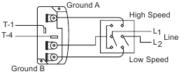
2 Speed, 2 Winding, Single Phase Motor
When ground is required, attach to ground A or B with No. 6 thread forming screw. To reverse, interchange T-1 and T-4 leads.
Single Speed, Single Phase, Dual Voltage
When ground is required, attach to ground A or B with No. 6 thread forming screw. To reverse, interchange T-5 and J-10 leads.

3-3 Phase, 9 Lead Motor
To reverse, interchange any 2 line leads.

2 Speed, 1 Winding, 3-Phase Motor
To reverse, interchange any 2 line leads. Motors require magnetic control.

2 Speed, 2 Winding, 3-Phase
To reverse: High Speed: interchange leads T11 and T12. Low Speed: interchange leads T1 and T2. Both Speeds: interchange any 2 line leads.

Typical Fan Motor/Damper Motor Schematic
For 3-Phase, damper motor voltage should be the same between L1 and L2. For single phase application, disregard L3.

*Damper motors may be available in 115, 230 and 460 volt models. The damper motor nameplate voltage should be verified prior to connection.
**A transformer may be provided in some installations to correct the damper motor voltage to the specified voltage.
Blade Angle Adjustment
Instructions for adjusting blade angle setting on adjustable pitch vane Axial Inline Blowers (AVA):
NOTICE! Verify that the fan at the new pitch does not operate at a critical speed (RPM) see table below.

The maximum safe blade angle setting for this fan is shown on the decal located inside the hub cover.
- Disconnect power supply.
- Remove hub cover.
- Placing a bubble protractor on the flat machined surface on the discharge side of the hub, take an initial reading. When setting the blade to the desired angle (no greater than 40°), remember to allow for the angle at which the fan is installed, as indicated by the initial reading.
- Adjust each blade individually as follows (note that one person should hold and adjust the blade while another tightens the nuts).
- Place blade in 3 o'clock or 9 o'clock position.
- Loosen retaining nut on blade bolt.
- Position bubble protractor on the face (discharge side) of the blade at the indicated line, If the line is not visible, position protractor on a line perpendicular to the blade center line, and 30% of the wheel radius in from the tip on 39", 49", 63" and 79" fans (33% on 35", 44" 55" and 71" fans).
- Set blade to desired angle, correcting for angle of installation.
- Tighten nut so that blade is snug.
- Recheck blade angle. If blade has shifted, tap blade near hub with soft mallet to correct.
- Tighten nut to tabulate torque (see following Torque chart).
- Rotate wheel to bring next blade into same position and repeat steps 5-12 until all blades are adjusted.
- Replace hub cover.
- Reconnect power supply.
| Bolt Size | Torque (FT-LB)* | |
| Minimum | Maximum | |
| 5/8" | 40 | 110 |
| 3/4" | 140 | 190 |
| 7/8" | 265 | 350 |
| 1" | 450 | 550 |
*For adjustment of blades only.
Propeller Rotation
Test the fan to ensure the rotation of the wheel is the same as indicated by the arrow marked Rotation.
115 and 230 Single Phase Motors
Fan wheel rotation is set correctly at the factory. Changing the rotation of this type of motor should only be attempted by a qualified electrician.
208, 230 and 460 3-Phase Motors
These motors are electrically reversible by switching two of the supply leads. For this reason, the rotation of the fan cannot be restricted to one direction at the factory. See Wiring Diagrams, for specific information on reversing wheel direction.
NOTICE! Do not allow the fan to run in the wrong direction. This will overheat the motor and cause serious damage. For 3-phase motors, if the fan is running in the wrong direction, check the control switch. It is possible to interchange two leads at this location so that the fan is operating in the correct direction.

AVA Critical Fan Speed (the AVA should not operate between the high and low RPM)

Final Installation Steps
- Inspect fasteners and setscrews, particularly fan mounting and bearing fasteners then tighten according to the Recommended Torque chart.
- Inspect for correct voltage with a voltmeter.
- Ensure all accessories are installed.
Operation
Pre-Start Checks
- Lock out all the primary and secondary power sources.
- Ensure fasteners and setscrews, particularly those used for mounting the fan, are tightened.
- Inspect belt tension and pulley alignment.
- Inspect motor wiring.
- Ensure belt touches only the pulleys.
- Ensure fan and ductwork are clean and free of debris.
- Inspect prop-to-inlet clearance. The correct prop-to-inlet clearance is critical to proper fan performance.
- Close and secure all access doors.
- Restore power to fan.
Start-Up
Turn on the fan. In variable speed units, set the fan to its lowest speed and inspect for the following:
- Direction of rotation
- Excessive vibration
- Unusual noise
- Bearing noise
- Improper belt alignment or tension (listen for squealing)
- Improper motor amperage or voltage
NOTICE! If a problem is discovered, immediately shut off the fan. Lock out all electrical power and check for the cause of the trouble. Refer to Troubleshooting.
Recommended Torque for Setscrews/Bolts (IN-LB)
| Setscrews | Hold Down Bolts | ||||
| Size | Key Hex Across Flats | Recommended Torque | Size | Recommended Torque | |
| Min. | Max. | ||||
| #8 | 5/64" | 15 | 21 | 3/8"-16 | 324 |
| #10 | 3/32" | 27 | 33 | 1/2"-13 | 780 |
| 1/4 | 1/8" | 70 | 80 | 5/8"-11 | 1440 |
| 5/16 | 5/32" | 140 | 160 | 3/4"-10 | 2400 |
| 3/8 | 3/16" | 250 | 290 | 7/8"-9 | 1920 |
| 7/16 | 7/32" | 355 | 405 | 1"-8 | 2700 |
| 1/2 | 1/4" | 560 | 640 | 1-1/8"-7 | 4200 |
| 5/8 | 5/16" | 1120 | 1280 | 1-1/4"-7 | 6000 |
| 3/4 | 3/8" | 1680 | 1920 | - | - |
| 7/8 | 1/2" | 4200 | 4800 | - | - |
| 1 | 9/16" | 5600 | 6400 | - | - |
This table is not to be used for blade angle adjustment.
Inspection
Inspection of the fan should be conducted at the first 30 minute, 8 hour and 24 hour intervals of satisfactory operation. During the inspections, stop the fan and inspect as per the Conditions Chart.
30 Minute Interval
Inspect bolts, setscrews and motor mounting bolts. Adjust and tighten as necessary.
8 Hour Interval
Inspect belt alignment and tension. Adjust and tighten as necessary.
24 Hour Interval
Inspect belt tension, bolts, setscrews and motor mounting bolts. Adjust and tighten as necessary.
Maintenance
Establish a schedule for inspecting all parts of the fan. The frequency of inspection depends on the operating conditions and location of the fan.
Inspect fans exhausting corrosive or contaminated air within the first month of operation. Fans exhausting contaminated air (airborne abrasives) should be inspected every three months.
Regular inspections are recommended for fans exhausting non-contaminated air.
It is recommended the following inspections be conducted twice per year:
- Inspect bolts and setscrews for tightness. Tighten as necessary.
- Inspect belt wear and alignment. Replace worn belts with new belts and adjust alignment as needed. Refer to Belt and Pulley Installation.
- Bearings should be inspected as recommended in the Lubrication Conditions Chart.
- Inspect springs and rubber isolators for deterioration and replace as needed.
- Inspect for cleanliness. Clean exterior surfaces only. Removing dust and grease on motor housing assures proper motor cooling. Removing dirt from the wheel and housing prevents imbalance and damage.
Lubrication
Fan Bearings
NOTICE! The fan bearings are provided prelubricated. Any specialized lubrication instructions on fan labels supersedes information provided herein. Bearing grease is a petroleum lubricant in a lithium base conforming to an NLGI #2 consistency. If user desires to utilize another type of lubricant, they take responsibility for flushing bearings and lines, and maintaining a lubricant that is compatible with the installation.
Vane Axial bearings are lubricated through a grease fitting on the exterior of the fan housing and should be lubricated by the schedule, Lubrication Conditions Chart.
For best results, lubricate the bearing while the fan is in operation. Pump grease in slowly until a slight bead forms around the bearing seals. Excessive grease can burst seals thus reducing bearing life.
Before lubricating, the grease nipple and immediate vicinity should be thoroughly cleaned without the use of high pressure equipment. The grease should be supplied slowly as the bearing rotates until fresh grease slips past the seal. Excessive pressure should be avoided to prevent seal damage.
Use no more than three injections with a hand-operated grease gun.
Lubrication Conditions Chart
| Fan Class | Fan Status | Fan Operating Temperature (F°) | Maximum Interval (operation hrs) |
| Inlet Vane Axial Blowers | Normal Conditions (clean, dry & smooth) | up to 120 | 4500 |
| 121–160 | 1500 | ||
| 161–200 | 700 | ||
| 201–400 (*) | 200 | ||
| Extreme Conditions (dirty/wet/rough) | up to 160 | 700 | |
| 161–200 | 400 | ||
| 201–400 (*) | 200 |
*Exceptions to the greasing interval chart:
- Periodic Applications (any break of one week or more): it is recommended that full lubrication be performed prior to each break in operation.
- Higher Temperature: it is recommended to halve the intervals for every 30°F increase in operating temperature above 120°F not to exceed 230°F for standard bearings; high temperature bearings (optional) can operate up to 400°F.
- Vertical Shaft: it is recommended that the intervals should be halved.
Loren Cook Company uses petroleum lubricant in a lithium base. Other types of grease should not be used unless the bearings and lines have been flushed clean. If another type of grease is used, it should be a lithium-based grease conforming to NLGI grade 2 consistency.
Motor Bearings
Motors are provided with prelubricated bearings. Any lubrication instructions shown on the motor nameplate supersede instructions below.
Motor bearings without provisions for relubrication will operate up to 10 years under normal conditions with no maintenance. In severe applications, high temperatures or excessive contaminates, it is advisable to have the maintenance department disassemble and lubricate the bearings after 3 years of operation to prevent interruption of service.
For motors with provisions for relubrication, follow intervals of the table below.
Relubrication Intervals
| Service Conditions | Nema Frame Size | |||||
| Up to and Including 184T | 213T-365T | 404T and Larger | ||||
| 1800 RPM and Less | Over 1800 RPM | 1800 RPM and Less | Over 1800 RPM | 1800 RPM and Less | Over 1800 RPM | |
| Standard | 3 yrs. | 6 months | 2 yrs. | 6 months | 1 yr. | 3 months |
| Severe | 1 yr. | 3 months | 1 yr. | 3 months | 6 months | 1 month |
Motors are provided with a polyurea mineral oil NGLI #2 grease. All additions to the motor bearings are to be with a compatible grease such as Exxon Mobil Polyrex EM and Chevron SRI.
The above intervals should be reduced to half for vertical shaft installations.
Motor Services
Should the motor prove defective within a one-year period, contact your local Loren Cook representative or your nearest authorized electric motor service representative.
Changing Shaft Speed
All belt driven AF fans with motors up to and including 5HP are equipped with variable pitch pulleys. To change the fan speed, perform the following:
- Loosen setscrew on driver (motor) pulley and remove key, if equipped.
- Turn the pulley rim to open or close the groove facing. If the pulley has multiple grooves, all must be adjusted to the same width.
- After adjustment, inspect for proper belt tension.
Speed Reduction
Open the pulley in order that the belt rides deeper in the groove (smaller pitch diameter).
Speed Increase
Close the pulley in order that the belt rides higher in the groove (larger pitch diameter). Ensure that the RPM limits of the fan and the horsepower limits of the motor are maintained.
Pulley and Belt Replacement
- Remove pulleys from their respective shafts.
- Clean the motor and fan shafts.
- Clean bores of pulleys & coat the bores with heavy oil.
- Remove grease, rust or burrs from the pulleys and shafts.
- Remove burrs from shaft by sanding.
- Place fan pulley on the fan shaft and the motor pulley on the motor shaft. Damage to the pulleys can occur when excessive force is used in placing the pulleys on their respective shafts.
- Tighten in place.
- Install belts on pulleys and align as described in Belt and Pulley Installation.
Bearing Replacement
- Loosen and remove belts by lowering motor mounting plate with the four adjusting nuts.
- Remove the bearing cover. Do not remove fan sheave yet.
- Remove prop by loosening setscrews and retaining bolts and sliding off shaft.
- Record the location of the fan sheave from end of shaft, and remove the sheave.
- Record the distance from the bearing to the end of the shaft.
- Loosen setscrews on bearings and remove shaft.
- Remove bearings and replace with new bearings.
- Slide shaft through bearings until shaft protrudes the same amount as original shaft. Tighten setscrews.
- Replace fan sheave in original location.
- Replace prop but do not tighten yet.
- Slide prop on shaft and center prop.
- Replace and tighten belts.
- Test run the fan.
- Re-tighten setscrews on bearings, sheave and prop. Recheck belt tension and adjust as needed.
- Replace bearing cover.
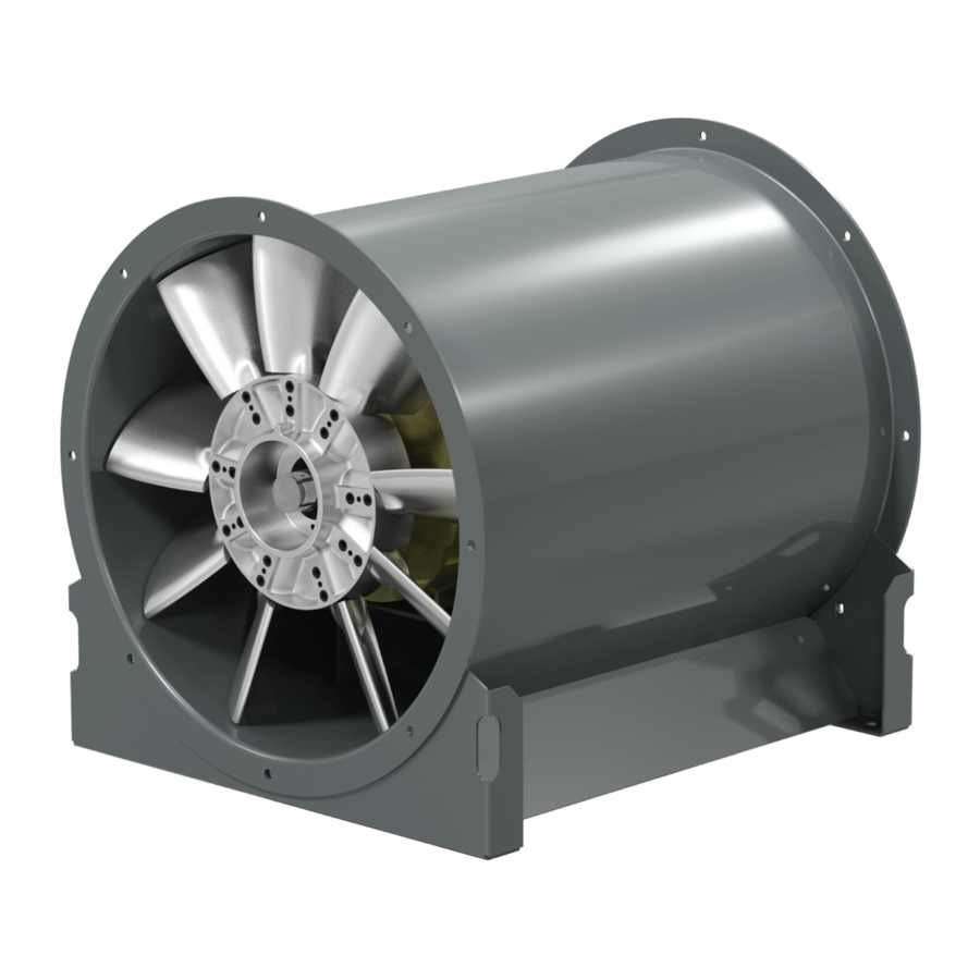
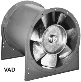
Parts List
VAD

| Part No. | Description |
| 1 | Drum Weldment |
| 2 | Propeller Fixed Pitch |
| 3 | Propeller Bushing |
| 4 | Motor |
| 5 | Wiring Box |
| 6 | Motor Mounting Bolts |
VAB

| Part No. | Description |
| 1 | Drum Weldment |
| 2 | Shaft |
| 3 | Bearing (2) |
| 4 | Propeller |
| 5 | Propeller Bushing |
| 6 | Belt Tunnel |
| 7 | Motor Plate |
| 8 | Inner Drum Nose |
| 9 | Motor |
| 10 | Drive Sheave |
| 11 | Driven Sheave |
| 12 | Belt |
VAHB

| Part No. | Description |
| 1 | Drum Weldment |
| 2 | Shaft |
| 3 | Bearing (2) |
| 4 | Propeller |
| 5 | Propeller Bushing |
| 6 | Belt Tunnel |
| 7 | Motor Plate |
| 8 | Inner Drum Nose |
| 9 | Motor |
| 10 | Drive Sheave |
| 11 | Driven Sheave |
| 12 | Belt |
AVAD

| Part No. | Description |
| 1 | Drum Weldment |
| 2 | Propeller |
| 3 | Propeller Bushing |
| 4 | Motor |
| 5 | Wiring Box |
| 6 | Motor Mounting Bolts |
AVAB

| Part No. | Description |
| 1 | Drum Weldment |
| 2 | Shaft |
| 3 | Bearing |
| 4 | Propeller |
| 5 | Propeller Bushing |
| 6 | Motor Plate |
| 7 | Inner Drum Nose |
| 8 | Motor |
| 9 | Drive Sheave |
| 10 | Driven Sheave |
| 11 | Belt |
| 12 | Belt Tunnel (2) |
AFB

| Part No. | Description |
| 1 | Drum Weldment |
| 2 | Shaft |
| 3 | Bearing |
| 4 | Motor Plate |
| 5 | Propeller C-Cast Bushing H-High Temperature Construction S-Stainless Steel Construction |
| 6 | Propeller Bushing |
| 7 | Bearing Cover |
| 8 | Motor |
| 9 | Drive Sheave |
| 10 | Driven Sheave |
| 11 | Belt |
AFBV

| Part No. | Description |
| 1 | Drum Weldment |
| 2 | Shaft |
| 3 | Bearing |
| 4 | Motor Plate |
| 5 | Propeller C-Cast Bushing H-High Temperature Construction S-Stainless Steel Construction |
| 6 | Propeller Bushing |
| 7 | Bearing Cover |
| 8 | Motor |
| 9 | Drive Sheave |
| 10 | Driven Sheave |
| 11 | Belt |
| 12 | Vane Section |
AFD-C

| Part No. | Description |
| 1 | Drum Weldment |
| 2 | Propeller |
| 3 | Prop Bushing |
| 4 | Motor |
| 5 | Motor Mounting Box |
AFDV-C

| Part No. | Description |
| 1 | Drum Weldment |
| 2 | Propeller |
| 3 | Prop Bushing |
| 4 | Motor |
| 5 | Motor Mounting Box |
| 6 | Vane Section |
Troubleshooting
Problem and Potential Cause
Low Capacity or Pressure
- Incorrect direction of rotation. Make sure the fan rotates in same direction as the arrows on the motor or belt drive assembly.
- Poor fan inlet conditions. There should be a straight clear duct at the inlet.
- Improper wheel alignment.
Excessive Vibration and Noise
- Damaged or unbalanced wheel.
- Belts too loose; worn or oily belts.
- Speed too high.
- Incorrect direction of rotation. Make sure the fan rotates in same direction as the arrows on the motor or belt drive assembly.
- Bearings need lubrication or replacement.
- Fan surge or incorrect inlet or outlet condition.
Overheated Motor
- Motor improperly wired.
- Incorrect direction of rotation. Make sure the fan rotates in same direction as the arrows on the motor or belt drive assembly.
- Cooling air diverted or blocked.
- Improper inlet clearance.
- Incorrect fan RPMs.
- Incorrect voltage.
Overheated Motor
- Improper bearing lubrication
- Excessive belt tension.

Rotating Parts & Electrical Shock Hazard:
Fans should be installed and serviced by qualified personnel only.
Disconnect electric power before working on unit (prior to removal of guards or entry into access doors).
Follow proper lockout/tagout procedures to ensure the unit cannot be energized while being installed or serviced.
A disconnect switch should be placed near the fan in order that the power can be swiftly cut off, in case of an emergency and in order that maintenance personnel are provided complete control of the power source.
Grounding is required. All field-installed wiring must be completed by qualified personnel. All field installed wiring must comply with National Electric Code (NFPA 70) and all applicable local codes. Ensure the power supply (voltage, frequency and current carrying capacity of wires) is in accordance with the motor nameplate.
Fans and blowers create pressure at the discharge and vacuum at the inlet. This may cause objects to get pulled into the unit and objects to be propelled rapidly from the discharge. The discharge should always be directed in a safe direction and inlets should not be left unguarded. Any object pulled into the inlet will become a projectile capable of causing serious injury or death.
When air is allowed to move through a non-powered fan, the impeller can rotate, which is referred to as windmilling. Windmilling will cause hazardous conditions due to unexpected rotation of components. Impellers should be blocked in position or air passages blocked to prevent draft when working on fans.
Friction and power loss inside rotating components will cause them to be a potential burn hazard. All components should be approached with caution and/or allowed to cool before contacting them for maintenance.
Under certain lighting conditions, rotating components may appear stationary. Components should be verified to be stationary in a safe manner, before they come into contact with personnel, tools or clothing.
Failure to follow these instructions could result in death or serious injury.
The attachment of roof mounted fans to the roof curb as well as the attachment of roof curbs to the building structure must exceed the structural requirements based on the environmental loading derived from the applicable building code for the site. The local code official may require variations from the recognized code based on local data. The licensed engineer of record will be responsible for prescribing the correct attachment based on construction materials, code requirements and environmental effects specific to the installation.
Corporate Offices: 2015 E. Dale St. Springfield, MO 65803
Phone 417-869-6474
Fax 417-862-3820
lorencook.com
Documents / Resources
References
Download manual
Here you can download full pdf version of manual, it may contain additional safety instructions, warranty information, FCC rules, etc.
Advertisement


Need help?
Do you have a question about the VA and is the answer not in the manual?
Questions and answers