Advertisement
- 1 Welcome
- 2 Product Description
- 3 Unpacking and Handling
- 4 Room Interaction
- 5 Listening
- 6 Connection
- 7 Signal Cable Options
- 8 Control Panel Operation
- 9 Amplification
- 10 SCM20ASL/ASLT Acoustic specification
- 11 SCM20PSL/PSLT Acoustic specification
- 12 Care and Maintenance
- 13 Contact
- 14 SAFETY WARNINGS
- 15 Documents / Resources
Welcome
In selecting ATC you have chosen an example of the finest audio engineering available. ATC was founded on a principle of engineering excellence, and that principle still defines our products today. Given the right opportunities, ATC products will deliver exceptional audio performance, but the opportunities will only arise from careful and thoughtful installation and use. Please read the following manual fully. It will help you understand the product and to realise its full potential. We are happy to answer questions and offer advice on any issues that arise through installation or use of ATC products. Contact details can be found at the back of this manual.
ATC was founded in London in 1974 by Australian emigre Billy Woodman. An enthusiastic pianist and engineer he was naturally drawn to loudspeaker design and after a period working at Goodmans, where many of the names that went on to found British loudspeaker companies began their careers, he struck out on his own. The premise on which ATC began is a simple one, and one that in many respects is still true today: hifi loudspeakers tend to be detailed and accurate but of limited dynamic range, while professional monitor speakers tend to express the opposite character. ATC products were designed from the outset to offer the best of both. It's an easy concept to describe, but surprisingly difficult to engineer.
The difficulty inherent in designing such loudspeakers is one of scale. Hifi levels of accuracy and detail call for lightweight moving parts and delicate engineering. Professional monitor levels of performance however demand far more robust components engineered to survive the rigours of high-level use for extended periods. The only way to combine the two is through precision engineering of a class and scale more often associated with aerospace or motor sport. But the results are worth the effort and the cost. ATC loudspeakers, with their unique in-house designed drivers, combine the best of hifi and professional to devastating effect.
ATC has become synonymous with active systems. Choosing to offer active loudspeakers (where the passive crossover network is replaced by active filters and multiple power amplifiers) is simply a result of the uncompromising attitude to loudspeaker design. While passive systems still have their place, and ATC engineering skills can still bring remarkable results from them, "active" is a fundamentally better solution to the problems posed by accurate, high level music reproduction. The ATC instinct is always for the better solution. Not cheaper, not quicker, but better.
It was the development of active loudspeakers that first brought ATC into electronics design and engineering. Active speakers demand multiple power amplifiers so, from the mid-1980s ATC became not just a loudspeaker manufacturing company but an electronics manufacturer too. The further step from electronics for active speakers to a range of stand-alone amplifier products was natural and now means that ATC engineering is available from the recording desk or CD player output to the ears.
From modest beginnings ATC has grown to become one of the very few manufacturers successful across both domestic and professional audio. By selecting ATC you join a group of music lovers, professional audio engineers, studios and musicians across the world that understand and value the engineering that goes into an ATC product – and the sound that comes out.
Product Description
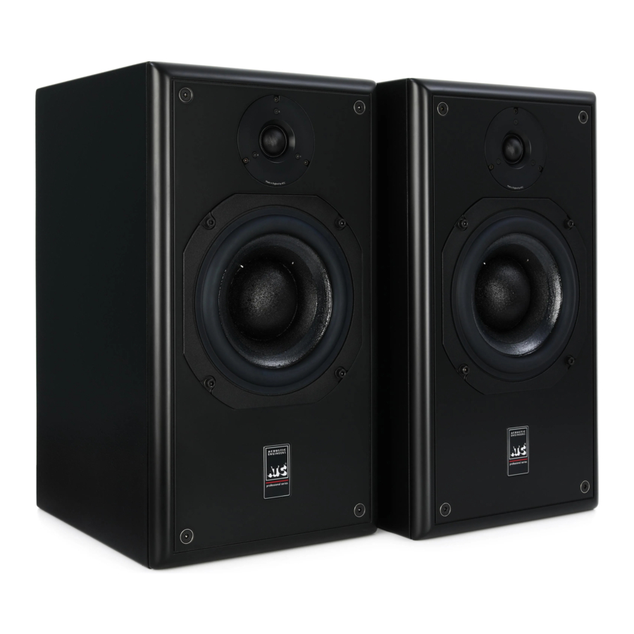
The SCM20 is a high-performance, 2-way loudspeaker available in both stand-mount and tower formats, with options for Passive or Active configurations. All versions feature the same compliment of proprietary drive units designed and manufactured in-house by ATC.
Frequencies below the 2.2kHz crossover are managed by the ATC SB75-150SL mid-bass driver. This exceptional driver features a highly damped 6-inch cone paired with an integrated 3-inch soft dome and utilises ATC's proprietary Super Linear Magnet Technology to significantly reduce odd-harmonic distortion, especially in the lower midrange. Designed with a large 3-inch voice coil and a short coil/long gap configuration, the SB75-150SL is capable of high dynamic range and outstanding power handling.
High frequencies are managed by ATC's SH25-76S high-performance 1-inch (25mm) soft dome tweeter. This advanced tweeter features a unique dual-suspension design that effectively suppresses mechanical rocking modes, enabling a tight tolerance magnetic gap without the need for ferrofluid. Paired with a highly optimised motor, featuring a large 60mm diameter neodymium ring magnet, this driver delivers exceptionally low odd-harmonic distortion and an extended frequency response.
The active SCM20ASL and SCM20ASLT feature a built-in two-way 'amp packs' with balanced inputs, active crossovers and a power amplifier dedicated to each drive unit.
The SCM20PSL and SCM20PSLT are equipped with a bi-wire connection panel, allowing for separate amplification of the mid-bass and high-frequency drivers if desired.
All models are offered in a range of high-quality veneered or painted finishes.
Unpacking and Handling
The SCM20 Classic and Tower are heavy items and should be handled with care. Two people are required to unpack the floor-standing 'Tower' SCM20ASLT/PSLT. It is recommended to unpack them on the floor covered by a soft surface such as carpet or a rug and with ample open space around the carton, ideally near their final installation location.
To unpack these loudspeakers, please follow the steps below:
STAND-MOUNT SPEAKER
- Open the carton and remove all loose items, leaving the foam in place. Take care to remove all staples from the box as they are sharp.
- Fold the flaps of the carton back and flip the carton over so the open end is facing down.
- Lift the carton off the contents, leaving the speaker and foam on the floor (speaker & foam 'endcaps').
- Being careful not to touch the front face of the loudspeaker, remove the upper foam end cap. Note: the ATC logo on the protective bag indicates the front face of the speaker.
- Un-tie the protective fabric bag, push the bag down towards the remaining foam end cap, again taking care not to damage the drive units. Flip the speaker & foam over so the speaker is standing on the floor.
- Remove the top foam end-cap.
- Remove the bag.
- Carefully lift the speaker into position taking care not to push against the drive units or knock the cabinet on any hard surfaces.
TOWER SPEAKER
- Open carton and remove all loose items, leaving the foam in place. Take care to remove all staples from the box as they are sharp.
- Fold the flaps of the carton back and flip the carton over so the open end is facing down.
- Lift the carton off the contents, leaving the speaker and foam on the floor (speaker & foam 'tray').
- Being careful not to touch the front face of the loudspeaker, remove the foam 'tray'. Note: the ATC logo on the protective bag indicates the front face of the speaker.
- Un-tie the protective fabric bag and open the end up to expose the base of the speaker. Slide the speaker to the edge of the foam 'tray'.
- Taking care not to damage the drive units, stand the speaker up on the floor.
- Remove the bag.
- Carefully lift the speaker into position taking care not to push against the drive units or knock the cabinet on any hard surfaces.
Tip! If your speaker stands have spikes, do not fit them until you have found the optimal position for the speakers.
Room Interaction
The room in which a loudspeaker is placed can be thought of as a filter, altering the acoustic response at the listening position from that of the loudspeaker. The position of the loudspeaker in a room will influence how it interacts with the space and therefore is often critical to achieving the best performance at the listening position.
Speaker positioning is important because at low frequencies the room will have a strong influence due to room modes/resonances. Room modes manifest themselves as an uneven distribution of acoustic energy within the room, which can lead to either too much or too little bass at the listening position.
A room with a well-controlled low frequency response (controlled reverb time) will have a far smaller influence on the performance of the loudspeaker and will be less sensitive to positioning. Applying acoustic treatment in a domestic setting is not always possible or desirable but if considered it should be noted that, typically, a combination of resonant membrane traps and porous absorbers are needed to control the low frequency. The resonant membrane traps are effective at treating the low bass, typically below 80Hz and the porous absorbers frequencies above this. Porous absorbers such as those made from foams, fibreglass or rockwool are not effective at absorbing low bass energy without a very large air space between them and the wall behind which reduces usable space within a room.
To minimise problems a free-standing loudspeaker should be kept away from corners where possible. Avoid placing the loudspeaker mid-way between any two parallel walls.
Typically, best results come from mounting stand-mount speakers on suitable speaker stands. Stands should be heavy, rigid, and non-resonant. Ensure that the stand can support the weight of the speaker and that the top-plate is large enough that the cabinet is stable. Ensure that the bottomplate is large enough so that the stand is stable with the load of the speaker on it. The stand height should be selected so that the speaker acoustic centre is at, or just above ear level (see diagram 1). Floor-standing 'Tower' speakers do not need stands.
Position the loudspeakers so they form an equilateral triangle with the listening position (see diagram 2). With this layout, the distance between the loudspeakers will be equal to the distance from one speaker to the listening position.
Listening
The ear and brain tend to interpret distorted sound as loudness and thus underestimate the actual level of undistorted sound. The SCM20PSL and SCM20ASL, like all ATC monitors, demonstrate much lower levels of distortion than conventional systems of a similar size and it is therefore advisable to begin listening at an artificially low level and carefully increase the volume. It is also possible for the monitors to produce sufficient sound pressure levels for your ears themselves to become a source of distortion and make the sound appear harsh. Any audible distortion indicates that either the system or your ears are being overloaded, and that the volume level should be reduced.
DIAGRAM 1

DIAGRAM 2

Connection
Two cable connections are required for each loudspeaker: one for mains power and one for the audio signal. The mains cable is specifically supplied to comply with local statutory safety approvals and alternatives should not be substituted. If you intend to use your loudspeakers in an alternative territory, please contact ATC for advice. The mains connection must always be earthed.
The signal cable(s) and plug(s) should be of a good quality and XLR terminated. Poor cable and plug quality will compromise the performance of your loudspeakers.
Signal Cable Options
Balanced cable configuration is the preferred option, however unbalanced connection is possible. Diagrams 3 & 4 illustrate the signal cable connections required for each option. Balanced (XLR-XLR) connection offers lower noise and better immunity to "hum" pick-up. Unbalanced (XLR-RCA Phono or two-pole jack) connection carries risk of "hum" caused by multiple signal earths. Hum problems resulting from unbalanced connection may be reduced by making ONE of the following modifications to the signal cable:
If the driving pre-amp is "double insulated" (i.e. has no mains earth), disconnect the signal cable screen at the RCA phono plug end.
Disconnect the signal cable screen at the XLR end. This option will make the source the reference signal earth.
DIAGRAM 3

DIAGRAM 4

Control Panel Operation
Power on/off
This button powers the loudspeaker on or off. When the switch is in the inward position the loudspeaker is powered on. When the switch is in the outward position the loudspeaker is powered off.
Due to the nature of the electronics in ATC active loudspeakers it is quite normal for a sound to be heard from the speaker when the power is applied or disconnected. The noise heard will not damage the speaker and is quite normal. Although ATC uses the highest-grade components, a different noise may be heard from each speaker due to slight tolerance variations in the amplifier components.
Mains Inlet
The supplied mains power lead (appropriate to the local territory) should be connected here. Ensure that the mains voltage specified on the panel corresponds with the local supply voltage.
DIAGRAM 5

Fuse Holder
Should a loudspeaker fail to switch on when the power switch is operated, the fuse should be inspected. Lift out the fuse holder cover using a small flat-blade screwdriver, remove the fuse and inspect for damage. If required, a replacement fuse should be fitted. Ratings are printed on the amp rear panel. It should be stressed, however, that fuses most often fail only because of a serious electrical fault. If this is the case, then simply replacing the fuse will only result in another fuse failure. In the case of a second fuse failure, please contact your local ATC representative in the first instance for support. Details can be found on the ATC website.
Input Socket
The audio signal cable should be connected here. Balanced or unbalanced cables may be used.
Input Sensitivity
This control adjusts the amp and speaker output level with respect to the input level. A higher sensitivity means less voltage is needed at the input for a given output level (higher gain). A lower sensitivity means more voltage is needed at the input for a given output level.
This user adjustment is made up of two controls:
- Selector Switch – This switch toggles between 1V/+2.2dBu and 2V/+8.2dBu input sensitivity (for full amp output). Choose the setting that best suits the source/pre-amp combination.
- Sensitivity Trim – Input sensitivity can be further fine-tuned using the Input Sensitivity Trim.
Note: For source (driving) equipment with potentiometer based analogue level control, choose an input sensitivity that results in the desired average sound pressure level with the source level control at approximately 50%. For source (driving) equipment with a digital level control, choose an input sensitivity that results in the desired average sound pressure level with the level control at approximately 80%.
Sensitivity Trim
This control provides fine adjustment of input sensitivity. Fully clockwise is the factory 'reference' position of 0dB. In this position, the trim has no effect on the input sensitivity which is controlled by the switch described above. Turning the control anti-clockwise will result in up to -6dB of adjustment.
The combination of the two controls gives a total input sensitivity range of 1V/+2.2dBu to 4V/+14.2dBu (for full amplifier output of 200W).
Bass Shelf
This adjustment provides -2dB to +3dB of cut and boost, in 1dB steps, in the form of a shelving filter. This subtracts/adds more warmth and energy in the low frequency region. The electrical response of the filter in the six different positions is shown in Diagram 6 below.
When used to boost it is at the expense of:
- Accurate transient reproduction
- Reduced Headroom
- Increased distortion
Note: This adjustment should be used for fine tuning. Please try to achieve the best possible in-room bass response by first adjusting loudspeaker and listening position and room acoustic treatment if possible.
DIAGRAM 6

Fault
Indicates a temporary or permanent amplifier fault. The Fault LED will illuminate if amplifier panel temperature exceeds 60 degrees C or if there is a DC fault on the amplifier.
In the rare case that the Fault LED illuminates:
- Switch the loudspeaker power off.
- Ensure the amplifier heatsink has adequate ventilation and allow to cool for 45 minutes.
If the Fault LED remains illuminated the amplifier is registering a DC offset fault within the power amplifier which should be investigated by an approved technician. Please contact your ATC dealer or distributor, details can be found at www.atc.audio. If the Fault LED is no longer illuminated, the amplifier shut down due to exceeding its safe operating temperature. Please reduce the system listening level and/or improve amplifier ventilation and continue to use the loudspeaker.
Connection
The SCM20PSL loudspeakers are equipped with a "bi-wire" connection panel to enable separate wiring/amplification of the mid-bass driver and tweeter. The connection panel is shown in Diagram 7 below.
Terminals can accommodate either stripped bare cable ends, 4mm banana plugs or spade terminals. Do not use ferrules on the bare wire ends as the difficulty in compressing them can cause poor link bar connection. Always use a good quality speaker cable with 2.5mm2 minimum cross-sectional area per conductor (79 strand). For cable runs longer than 5m use a significantly heavier gauge cable. Consult your dealer or consultant for specific cable recommendations. Ensure that the positive and negative terminals on each connection panel are connected to the corresponding positive and negative terminals on the amplifier.
If you are using conventional speaker cable with a single pair of conductors and a single integrated or power amplifier, first check that the link bars are in place between the vertical pairs of terminals. Connect the positive conductor of your speaker cable to either of the red terminals. Connect the negative conductor to either of the black terminals.
A lack of bass output and very wide unstable stereo imagine is most likely caused by the left and right loudspeakers being connected out of phase. If the system displays these characteristics, please check the polarity of the wiring.
DIAGRAM 7

If you wish to bi-wire or bi-amp, remove the linking bars, between vertical pairs of terminals. The upper horizontal pair of terminals are connected to the tweeter. The lower horizontal pair are connected to the bass driver. The connection panel for bi-wire configuration is shown in Diagram 8 below. For bi-amp systems it is VITAL that the two amplifiers used have equal gain. If you use amps with different gain, this will modify the frequency response of the loudspeaker. The two amps can have different maximum power outputs and it is best to use the more powerful amp to drive the bass section.
DIAGRAM 8

Amplification
The choice of partnering amplifier to power the SCM20PSL loudspeakers will have considerable influence on the performance of the system. Consider the following when selecting an amplifier:
- With any passive loudspeaker there is a trade-off between low frequency extension and sensitivity. These monitor's extended low frequency response means the sensitivity is relatively low, although this is countered by the 8Ω impedance. It is therefore advisable to select a power amplifier of relatively high-power output capabilities. An amplifier capable of delivering 75W-300W into 8Ω is recommended.
- Use of an underpowered amplifier will result in the premature distortion of the system and increased risk of damage due to voice coil overheating
- Valve or solid-state amplifiers with high output impedances should be auditioned carefully, to establish that their characteristic reduced damping factor at low frequencies is acceptable.
- Thanks in part to Super Linear technology and the underhung voice coil construction, these monitors not only demonstrate extremely low distortion at all levels, but also a greatly enhanced effective dynamic range. This exceptional distortion performance, combined with a very wide dispersion will ruthlessly reveal deficiencies in ancillary equipment. It is advisable, therefore, to audition the loudspeakers with your proposed amplifier and ancillary system.
SCM20ASL/ASLT Acoustic specification
Drive units
Mid-Bass: 1 x SB75-150SL 8Ω
HF: 1 x SH25-76S 6Ω
Low Frequency Cut-off: 55Hz (-6dB, anechoic)
High Frequency Cut-off: 25kHz (-6dB)
Matched Response: +/-0.5dB
Crossover Point: 2.2kHz
MaxSPL: 108dB continuous, 114dB peak (per pair, IEC Weighted Pink Noise, 1m, anechoic)
System Sensitivity: 85dBC SPL (@1m, pink noise, -18dBu, 1V input sens. 0dB bass boost)
SCM20ASL/ASLT Electronic specification
Balanced Input: 1 x rear panel mounted female XLR, pin 2 hot
Input Impedance: 20kΩ (differential)
Input CMRR: >60dB (10kHz)
Input Sensitivity: 2.2dBu/1Vrms for full power
Input Sensitivity Control: -6dB switchable, -6dB variable. Total adjustment 2.2dBu/1Vrms to 14.2dBu/4Vrms
Bass Shelf: -2dB to +3dB, switchable in 1dB steps
Crossover Filters: 2nd Order Linkwitz Riley
Amplifier type: Grounded Source MOSFET based Class A/B, convection cooled
Output Power: Bass 200W into (8Ω), HF 50W into (8Ω)
THD+N: <0.0017%/-95dB (1kHz, 1dB below rated power, 90kHz BW)
Frequency Response: <2Hz to >200kHz (-3dB)
Limiter: ATC Active FET Momentary Gain Reduction
Electronic amp protection: Amplifier d.c. offset and over-temperature (both indicated by rear panel LED) Mains Input: 220-230V or 115V – Factory set. Please observe panel markings and labels!
Power Consumption: Idle 26W/41VA, 1/8th Power 116W/161VA, Full Power 312W/398VA Heat Output: Idle 89BTU/hr, 1/8th Power 311BTU/hr, Full Power 382BTU/hr
For physical specifications see diagrams on following pages
SCM20ASL WEIGHT 24.3KG/53.6 LBS – DIMENSIONS SEE DIAGRAM

SCM20ASLT 30.2KG/ 66.6LBS – DIMENSIONS SEE DIAGRAM

SCM20PSL/PSLT Acoustic specification
Drive units
Mid-Bass: 1 x SB75-150SL 8Ω
HF: 1 x SH25 - 76S 6Ω
Low Frequency Cut-off: 55H z (- 6 d B, anechoic)
High Frequency Cut-off: 25 k H z (- 6 d B )
Matched Response: +/- 0. 5 d B
Crossover Point: 2. 2 k H z
MaxSPL: 108 d B continuous, 114 d B peak (per pair, IEC Weighted Pink Noise, 1m, anechoic)
Sensitivity: 85 d B ( 1W @1m)
SCM20PSL/PSLT Electronic specification
Recommended Power Amplifier: 75W - 300W
Impedance: 8Ω nominal/ 5. 5Ω minimum
For physical specifications see diagrams on following pages
SCM20PSL WEIGHT 16.9KG/37.3LBS – DIMENSIONS SEE DIAGRAM

SCM20PSLT 24.7KG / 54.5LBS – DIMENSIONS SEE DIAGRAM

Care and Maintenance
High technology material finishes are used in this product. The cabinet and amplifier surfaces are durable and with a little care can be kept as good as new even under conditions of heavy use. Normally, a dry duster will be all that is required to keep the cabinet and amplifier finishes clean.
Heavy soiling of the cabinet or baffle can be cleaned using a cloth slightly moistened with a non-abrasive household cleaner.
There are no components within the speakers that can be considered expendable, or that would benefit from regular maintenance. There is no requirement for any kind of routine service work and there is no schedule for preventative maintenance. There are no user-replaceable parts within the speaker, and in the unfortunate event of any malfunction, repair should be referred to either the supplying dealer or consultant, the relevant importer, or ATC. ATC has every confidence in the quality of each product that it manufactures.
Contact
Loudspeaker Technology Ltd
Gypsy Lane, Aston Down Stroud, Gloucestershire
GL6 8HR
United Kingdom
Telephone +44 (0)1285 760561
Email: info@atc.audio
Website: www.atc.audio
SAFETY WARNINGS
- Read instructions – all the safety and operating instructions should be read before the appliance is operated.
- Retain these instructions – the safety and operating instructions should be retained for future reference.
- Respect warnings – all warnings on the appliance and in the operating instructions should be adhered to.
- Follow instructions – all operating and other instructions should be followed.
- Water and moisture – the appliance should not be used near water, for example near a bathtub, wash bowl, kitchen sink, laundry tub, in a wet basement or near a swimming pool etc.
- Ventilation – the appliance should be situated so that its location or position does not interfere with its proper ventilation. For example, the appliance should not be situated on a bed, sofa, or similar surface that may block the ventilation openings. Similarly, the appliance should not be built into an installation, such as a bookcase or cabinet, that may impede the flow of air through the ventilation openings.
- Heat – the appliance should be situated away from heat sources such as radiators, stoves or other appliances that produce heat.
- Power sources – the appliance should be connected to a power supply only of the type described in the operating instructions or as marked on the appliance.
- Power cord protection – power supply cords should be routed so that they are not likely to be walked on or pinched by items placed upon or against them, paying particular attention to cords at plugs, convenience receptacles and the point where they exit the appliance.
- Cleaning – the appliance should be cleaned only as recommended by the manufacturer.
- Unattended periods – the power cord of the appliance should be unplugged from the outlet when left unused for a long period of time.
- Object and liquid entry – care should be taken so that objects and liquids do not fall into the appliance.
- Damage requiring service – the appliance should be serviced by qualified service personnel when: i the power supply cord or the plug has been damaged ii objects have fallen or liquid has been spilled into the appliance iii the appliance has been exposed to rain or other serious liquid exposure iv the appliance does not appear to operate normally or exhibits a marked change in performance v the appliance has been dropped or the cabinet damaged.
- Servicing – the user should not attempt to service the appliance beyond those measures described in the operating instructions. All other servicing should be referred to qualified service personnel. Please contact your local ATC dealer or distributor.
- Grounding – the appliance must be grounded (connected to mains safety earth) at all times.
- Polarisation – the polarity of the mains power connection must not be modified.
Documents / Resources
References
Download manual
Here you can download full pdf version of manual, it may contain additional safety instructions, warranty information, FCC rules, etc.
Download ATC SCM20, SCM20ASL, SCM20ASLT, SCM20PSL, SCM20PSLT Manual
Advertisement


Need help?
Do you have a question about the SCM20 and is the answer not in the manual?
Questions and answers