Anker SOLIX Manual
- Installation manual (36 pages) ,
- Installation instructions manual (12 pages)
Advertisement
Disclaimer
We strongly recommend that you carefully read the safety regulations, installation instructions, and watch the installation video.
During the installation process, it is necessary to follow the safety regulations and installation instructions to ensure that all connections are firm and reliable. If you are not familiar with electrical installation, we strongly recommend that you seek the help of professional electricians. They have relevant knowledge and experience to ensure the safety and correctness of the installation process. Please note that incorrect installation may cause equipment damage, electrical failures, and even injury. Therefore, for your safety and the normal operation of the equipment, please operate with caution.
What's in the Box

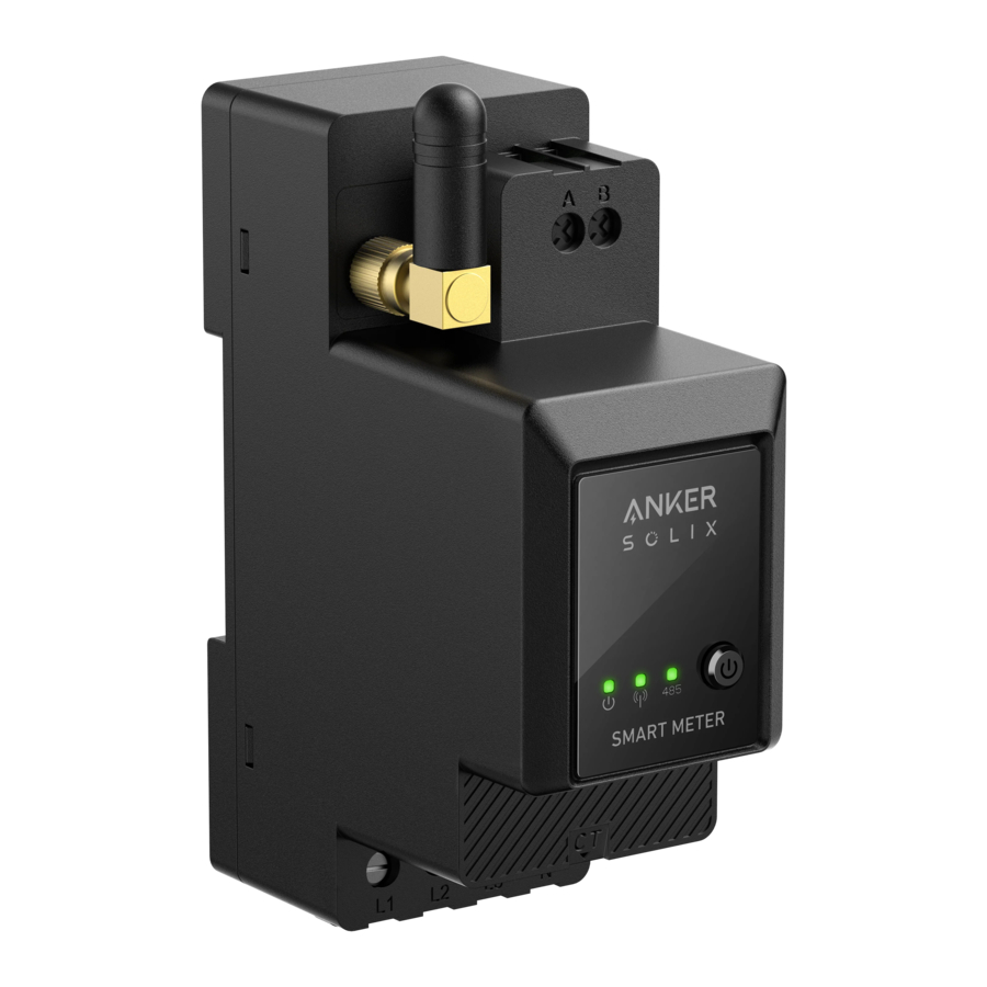
Overview
Product Overview
Anker SOLIX Smart Meter series is a line of devices suitable for homes, offices, retail stores, manufacturing facilities, and other buildings. Anker SOLIX Smart Meter devices are DIN mountable inside the breaker box and highly suitable for new building construction. Anker SOLIX Smart Meter devices can be controlled and monitored through Wi-Fi and LAN connections. Bluetooth connection can be used for the inclusion process. Anker SOLIX Smart Meter is a DIN rail mountable three-phase energy meter. The device reports accumulated energy as well as voltage, current, power factor data in real time. It stores data in non-volatile memory for later retrieval at least 60 days of 1 min data resolution.

- Voltage L1 Input (brown)
- Voltage L2 Input (black)
- Voltage L3 (gray) and Device Power Supply Input
- Neutral Input
- CT Port
- On/Off Switch
- Status Indicator
- Wi-Fi / Bluetooth Indicator
- RS485 Indicator
- RS485 A Through Hole
- RS485 B Through Hole
- Antenna
- CT1
- CT2
- CT3
- CT Link
- Extension Antenna
Installing the Smart Meter
Installation Instructions

- Danger of electrocution. Mounting/installation of the device to the power grid has to be performed with caution by a qualified electrician.
- Danger of electrocution. Ensure there is no voltage present at the device terminals before making any connection change.
- Use the device only with a power grid and appliances which comply with all applicable regulations. A short circuit in the power grid or any appliance connected to the device may damage it.
- Do not connect the device to appliances exceeding the given max load.
- Connect the device only in the way shown in these instructions. Any other method could cause damage and/or injury.
- Do not install the device where it can get wet.
- RECOMMENDATION: Connect the device using solid single-core cables with increased insulation heat resistance no less than PVC-T 105°C (221°F). Before starting the mounting/installation of the device, check that the breakers are turned off and there is no voltage from their terminals. This can be done with a phase tester or multimeter. When you are sure that there is no voltage, you can proceed to connecting the cables. Follow the diagram in fig. 1 to install the current transformers CT L1 around the Phase L1 cable to the load(s), CT L2 around the Phase L2 cable to the load(s) and CT L3 around Phase L3 cable to the load(s). Mount the device onto the DIN rail. Plug the cables of the CT L1, CT L2 and CT L3 into the Device L1, L2 and L3 input connectors respectively.
- Mount circuit breakers in accordance with your local regulations and connect Phase L1, Phase L2, and Phase L3 cables through them to the Device L1, L2 and L3 inputs respectively. Connect the neutral cable to the N input. The device is powered through its L1, L2, L3 input. Make sure you have made all the connections correctly and then turn on the circuit breakers.
Do not allow children to play with the buttons/switch connected to the device. Keep the devices for remote control of Anker SOLIX products away from children.
Connecting Cables
Please snap the CT to the phase cables on the household side. The cables are thick, and the specifications for the household side L1/L2/L3 are 63A with a maximum of 100A.
 Note:
Note:
- Install a voltage cable (sold separately).
- A three-phase smart meter can be used as a single-phase smart meter.
- Please first identify the entry phases.

Under normal circumstances, the brown phase is live wire L1, the black phase is live wire L2, the gray phase is live wire L3, and the blue phase is the neutral wire N.
![]()


| (International Standard) New House - Common Scenarios | (Old German Standard) Old House - Rare Scenarios |
| Brown----Live Wire L1 | Red----Live Wire L1 |
| Black----Live Wire L2 | Yellow----Live Wire L2 |
| Gray----Live Wire L3 | Blue----Live Wire L3 |
| Blue----Neutral Wire N | Black----Neutral Wire N |
| Green and Yellow----GND PE | Green and Yellow----GND PE |
- Turn off the power to ensure there is no risk of electric shock.
![]()
- Wear insulating gloves (provided by the user), and take out the Smart Meter and the CT (current transformer) from the package.
![]()
- Insert the Smart Meter into the distribution box rail, making sure it is securely fastened.

- Please prepare the corresponding color voltage wire, then connect the voltage wire from any unused circuit breaker hole and connect it to the hole of the corresponding Smart Meter.

- Connect the CT wire to the CT socket.

- Snap the CT to L1/L2/L3 phases.


Note: Please pay attention to the direction of the current.
- Snap L1 CT to L1 in the direction of the current.
- Snap L2 CT to L2 in the direction of the current.
- Snap L3 CT to L3 in the direction of the current.


LED Indicator
 | The connection between the Smart Meter and the distribution box has been completed. |
 | When the Smart Meter is connected to the CT and the CT is snapped to the corresponding phases, the CT automatically detects the current. |
 | Network configuration completed. |
 | Connection successful. |
Note: After successful connection, the Smart Meter is automatically powered on. If the user does not use the App for network configuration within 30 minutes, it will be turned off automatically.
Using the App
Download the App
Search "Anker" and download the Anker app via App Store

or Google Play

Or scan the QR code below to go to your App store.

Account Registration
Region Selection
When the App is successfully launched, you will head to the login page.
Please be reminded that the country region MUST match where you live. An incorrect country region may cause the device connection to fail.

Sign Up / Sign In
You can login via Anker account, Amazon, or Apple ID. If you do not have an Anker account, tap [Sign Up] to register an account:
Please input your email for the registration process. Passwords must contain 8-20 characters, uppercase and lowercase letters, numbers, and symbols.
Network Configuration
Before configuring, please ensure the network connection is working well with a strong Wi-Fi signal. Do not place the device far away from the router.
Add a Device
Step 1
- Keep the device on.
- Tap [+] or [Add Device] at the top right corner of Devices page.
![]()

Step 2
The Anker App will automatically search for your Smart Meter. Once the device is found, it will appear on the list.
- Please make sure your phone's Bluetooth is on, and the Anker app is authorized to access Bluetooth and Wi-Fi.
- If you wish to manually search for the device, you can tap [Accessory] in the "Add devices manually" row.
![]()

Step 3
After connecting Smart Meter via Bluetooth, you should choose a Wi-Fi network for the device. Select the Wi-Fi network from the list and enter the password.
- The device only supports 2.4GHz Wi-Fi.
- Make sure the password is correct.
![]()

Step 4
Your Smart Meter should successfully be configured to the network.
If the configuration process fails, follow the tips below:
- Check if the Wi-Fi router is working normally.
- Move the router closer to the device.
- Make sure the Wi-Fi password is correct.
![]()

Firmware Update
Make sure all your devices have configured Wi-Fi and have a stable network connection.
- If there is an important update for the firmware of Smart Meter, the App will guide you to through the process. Make sure your devices are on and connected to Wi-Fi before updating.

- If no update is required, you can skip this step.

Note:
Updates can take a few minutes. Please be patient. If the update fails, check if your devices are activated and connected to WiFi.
Energy Plan Setting
Once you have configured the Smart Meter, you can select Self-Consumption mode. The meter will intelligently manage Solarbank's discharging and energy storage in real time by obtaining only the amount of electricity required by household loads, not wasting solar energy.
Select Mode

Access mode selection from the energy plan shortcut on the Home page:
- Self-Consumption: In this mode, the Smart Meter calculates the power needed for household loads and sends it to Solarbank for efficient use of solar energy. Excess power is stored in the battery. This mode is only possible with a Smart Meter.
- Custom Mode: Manually create an electricity plan. Solarbank discharges household loads based on your inputs for different hourly timeframes. Extra energy is stored in the battery.
- An energy plan can be set for each day of the week for a flexible energy solution for your family.
- If there are currently Home Systems that can be added, you can choose to join the corresponding Home System.
* Note: If the Smart Meter is not added to a Home System, the Select Mode step will be skipped.
Custom Mode

Select Custom Mode, then click the button below it:
- Tap [Settings] to enter the energy plan setting page, which will list all the plans you have set up. If there is no plan, Solarbank will discharge 200W to home loads at all times.
- Click [+] in the upper right corner to add an electricity usage plan.
- On the energy plan page, tap [Set a Schedule] to set the power that Solarbank discharges to household loads for different time periods.
- Tap [Repeat] above to repeat the set discharge plan for other weeks.
- After completing all settings, tap [√ ] in the upper right corner to save and apply the Energy Plan.
Notes:
- You can add an energy plan for multiple devices with different recurring dates.
- Ensure that your device is connected to Wi-Fi when you save an electricity usage plan to synchronize the plan.
- In Self-Consumption mode, if the Smart Meter goes offline or malfunctions, Solarbank automatically switches to Custom mode as a backup energy plan. This lasts until the Smart Meter returns to normal, and then Self-Consumption mode automatically resumes.
Resetting the Network Configuration
Press the On/Off button for 7s to set the network configuration.

Specification
| AC Rated Input | 3× 230/400VAC, 50/60Hz, CT 40mA, 2W CATIII |
| Operating Temperature | -25°C to 55°C |
| DIN Rail | 35mm |
Documents / Resources
References
Download manual
Here you can download full pdf version of manual, it may contain additional safety instructions, warranty information, FCC rules, etc.
Advertisement


Need help?
Do you have a question about the SOLIX and is the answer not in the manual?
Questions and answers