Advertisement
Kit Contents
Upon receiving your kit, inspect all components to ensure they are present and undamaged.

Standard kit contents
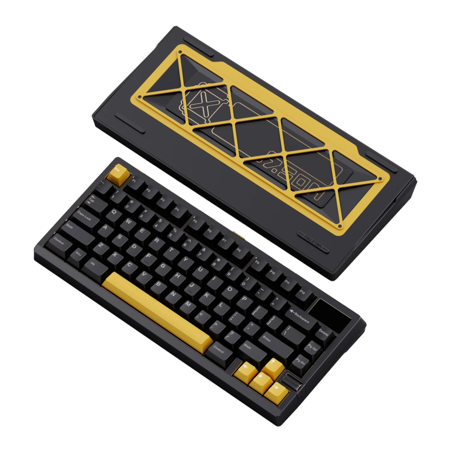
- Case Components:
- Top case (preinstalled with LCD screen and roller knob)
- Bottom case (preinstalled with batteries, internal weight, dual wing accents, soul grill, external weight, and silicone feet)
- Dampening Foam Kit (varies by selection): PET case foam, PET acoustic pad, case foam, switch foam, plate foam.
- PCB (preinstalled with magnetic strip and ribbon cables for LCD screen and roller knob)
- 2.4 GHz Receiver
- Plate (varies by selection)
- Stabilizers
- Mounting Options:
- Top mount
- Split O-Ring
- Elastic Bar Silicone
- Silica Gel Particle
- Additional Components:
- Screwdriver
- Magnetic rear badge
- Spare ribbon cables
- LCD screen and roller knob spacers
- Stabilizer pads
- USB cable
- Manual
- After-sales service card
Note:
- Inspect the case for defects before assembly. Refer to the quality disclaimer for acceptable tolerances.
- Switches and keycaps are not included in the kit and must be purchased separately.
Installation steps
Test PCB
Testing the PCB before assembly ensures functionality and prevents unnecessary troubleshooting later.
Skipping this step may void your replacement eligibility.
To test the PCB:
- Connect the PCB to the magnetic daughterboard in the bottom case.
- Connect the USB cable to the daughterboard.
- Open a Chromium-based browser (Chrome, Edge) and navigate to VIA's Key Tester tab.
- Flip the PCB over and use metal tweezers (or any conductive tool) to touch both contacts of each hotswap socket. The corresponding key should be highlighted in VIA.
If any socket fails to highlight, please contact Meletrix support for assistance.
Note:
- The Fn key will not highlight on the Key Tester without the Test Matrix option enabled, this is expected behaviour
To test the PCB wireless functionality:
- Insert switches into the Fn, Z, X, and C positions.
- Press and hold Fn+Z for 3 to 5 seconds, until the LED under Z flashes rapidly to indicate it is in pairing mode

- Connect to the Zoom75 TIGA on a suitable Bluetooth enabled device to confirm operation. The keyboard should appear as "Zoom75 TIGA BT1". After a successful pairing, the LED stays on for 3 seconds before turning off
- Repeat for X and C for the remaining two bluetooth channels

Note:
- Take care when inserting switches that the PCB is either flat on a surface or support the back of the hotswap sockets to ensure the socket does not pop off the PCB
To test the 2.4 GHz wireless functionality:
- Insert a switch into the V position.
- Press and hold Fn+V for 3 to 5 seconds, until the LED under V flashes rapidly to indicate it is in pairing mode

- Insert the 2.4 GHz receiver into the computer's USB port
- After a successful pairing, the LED stays on for 3 seconds before turning off

Note:
- If pairing fails, move the keyboard closer to the receiver and remove other 2.4 GHz receivers during pairing.
Use Fn+Space to return to wired mode
Assemble the internal components
- Place the clear PET case foam sheet on top of the PCB

- Position the PET acoustic pad on top of the case foam.

- Insert switches in the top-left and bottom-right sockets to align the layers

- Install the stabilizers:

- Align the non-threaded/non-clip side with the larger hole.
- Lower the screw/clip side into the smaller hole.
- Tighten screws (if using screw-in stabilizers) or press clips into place.
- If using screw-in stabilizers, install washers to prevent PCB shorts.
- If using clip-in stabilizers, insert stopper wedges to prevent detachment.


Note:
- Take care to test the stabilizers at this point to make sure they are able to move freely. This avoids having to disassemble the board later to fix any issues. To test, insert a switch between the stabilizer and mount a keycap. Ensure the keycap returns to its position smoothly.

- The number of stabilizers required will vary based on your chosen layout.

- Place the plate foam on top of the PCB (frosted/rough side up). Do not remove the transparent backing.

- Remove the spacers for the screen and knob plate from the packaging and install them on the bottom case. The hollow part should be facing up.

- Attach standoffs to the plate (optional but recommended for PC and POM plates). PC, POM, brass and aluminium plates use single headed screws, FR4 and carbon fibre use double headed screws.

- Secure the Plate to the PCB with screws

- For Poron foam kit, remove the transparent backing and place the case foam on the back of the PCB ensuring that it's correctly aligned with the PCB hot swap sockets. For other kits, do not remove the transparent backing, leave it in place.

- Peel off the blue backing from the Poron case foam, ensuring not to tear the foam. Not all case foams will have a blue backing.
This is a good time to insert your switches into the sockets, ensuring you brace the back of the PCB on a flat surface or support with your hands to prevent damage to the hot swap sockets. If you plan on using the LCD screen, do not insert the two switches on the top right corner of the PCB.

- Remove the Silica Gel Particle mounting from the packaging.

- Insert the particles into the grooves on the plate

- Align the PCB with the bottom case and place it into position.

- Install the screen and knob daughterboards, taking care to ensure they are seated in the spacers

- Align and press down the top case until it snaps into position on the ball catches.

- Attach the magnetic rear badge.

- Finally, mount your chosen keycap set!


And you're done! :)
Additional assembly

For details on alternative mounting options and additional modifications, refer to the official build video.
Note that the optional Lego/Pop Art stand is screwed into the rear magnetic badge holder.
Configuration
Customization, including key mapping, RGB settings, and screen content, is managed via VIA or the Zoom75 TIGA Console. We recommend VIA for setting key mapping, layers and macros, while screen configuration is exclusive to the Console and Pocket Wuque.
For best results, we recommend using this guide alongside the official build video. If this is your first time building a mechanical keyboard, carefully review both the guide and video before beginning to ensure a smooth assembly process.
If you experience any issues or require assistance, please contact Meletrix at service@meletrix.com or join our Discord server.
Documents / ResourcesDownload manual
Here you can download full pdf version of manual, it may contain additional safety instructions, warranty information, FCC rules, etc.
Advertisement

Need help?
Do you have a question about the Zoom75 TIGA and is the answer not in the manual?
Questions and answers