ARRI ALEXA 35 Live, LPS-1, TLM-1, LLA-1 Manual
- Operating manual (44 pages)
Advertisement
Product Information Resources
The ARRI documentation portal provides important documents on the product for free download.
Please enter the following searchkeys in the search bar to retrieve the documents for the product:
LPS-1, FCA-1, FBS-1, TLM-1, LLA-1,
K2.0050656, K2.0051099, K0.005107

ARRI documentation portal
For more details about the product, please refer to the ARRI website at:

ALEXA 35 Live
About the Product
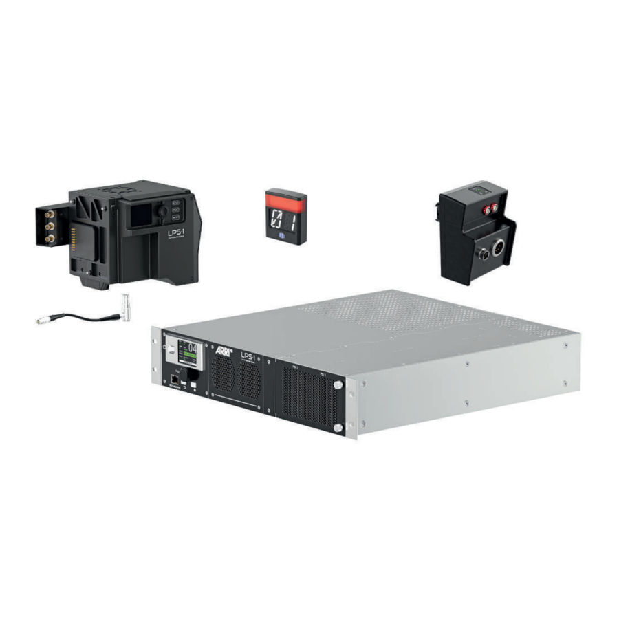
The ALEXA 35 Live - Multicam System consists of an ALEXA 35 Live (or an ALEXA 35), the Fiber Camera Adapter FCA-1, the Fiber Base Station FBS-1 and accessories. The description of the accessories Tally Light Module TLM-1 and the Large Lens Adapter LLA-1 Control Module is included in this operating manual.
The Fiber Camera Adapter FCA-1 and Fiber Base Station FBS-1 can be connected either with a hybrid fiber cable that delivers both power and uncompressed 4K video over distances up to 2 km, or with suitable adapters, with a tactical fiber cable up to 10 km in length. An extra fiber tunnel and Ethernet tunnel increase the system's flexibility with additional video, audio, or control signals.
Audience and Intended Use
The combination of a digital camera like ALEXA 35, FBS-1, FCA-1 and fiber cable is intended for a camera use where the system is integrated into a professional production environment, e.g. live broadcast from sport events. The system transmits live data from the camera to a control room and in reverse control commands from the control room to the camera. The main components of the ALEXA 35 Live - Multicam System are
- An ARRI ALEXA 35 Live digital camera with mounted Fiber Camera Adapter FCA-1,
- a Fiber Base Station FBS-1, and
- a SMPTE 311 hybrid cable to transmit image and control data and to supply the camera and accessories with power up to 400 W.
 NOTICE
All versions of the ALEXA 35 Live - Multicam System and its accessories are intended exclusively for professional use. It must be used only by skilled and trained personnel. The product and its accessories must not be used by inexperienced users and without proper training.
Read and understand the operating manual and the user manual before use.
Use the product and its accessories only for the purpose described in this document. Always follow the safety instructions and system requirements for all equipment involved. ARRI assumes no liability for damages or changes that are caused by improper use. You are not allowed to modify the product and its accessories.
Identification

Identification Fiber Camera Adapter FCA-1
The Fiber Camera Adapter FCA-1 serial number is located on type plate on the bottom of the adapter.
The serial number consists of the last 4 digits of the product number K2.0051089-101XX (here 101XX).

Identification Fiber Base Station FBS-1
The Fiber Base Station FBS-1 serial number is located on the type plate on the top of the housing and replicated on the left rear side.
The serial number consists of the last 4 digits of the product number K2.0051088-101XX (here 101XX).
Environmental Conditions
The Fiber Camera Adapter FCA-1 and the Fiber Base Station FBS-1 should only be used and stored under certain environmental conditions.
Check the following conditions before commissioning and operation:
| Fiber Camera Adapter FCA-1 | |
| Permissible Operating Temperature | -20°C to +45°C / -4°F to +113°F |
| Permissible Storage Temperature | -30°C to +70°C / -22°F to +158°F |
| Permissible Humidity | 0 - 95% rH from -20°C to +45°C (without condensation) 0 - 95% rH from -4°F to +113°F (without condensation) |
| Fiber Base Station FBS-1 | |
| Permissible Operating Temperature | 0°C to +40°C / 32°F to +104°F |
| Permissible Storage Temperature | -30°C to +70°C / -22°F to +158°F |
| Permissible Humidity | 0 - 95% rH from 0°C to +40°C (without condensation) 0 - 95% rH from 32°F to +104°F (without condensation) |
Technical Data
| Fiber Camera Adapter FCA-1 | |
| Video Outputs | 1x 12G, 3G or 1.5G Camera SDI 1 Out (BNC) 1x 3G or 1.5G Return Video SDI Out (BNC) 1x 12G, 3G or 1.5G AUX / Teleprompt Out (BNC) |
| Video Inputs | 2x 12G, 3G or 1.5G SDI (BNC) |
| Audio Outputs | 1x Line / AES (XLR) Embedded Audio on all SDI Outputs |
| Audio Inputs | 2x Line / AES (XLR) |
| Genlock | 1x REF OUT (Black Burst / Tri-Level) (BNC) |
| SMPTE Fiber | 3K Series LEMO Connector (max. Cable Length 2 km) |
| Additional Interfaces | 1x AUX Fiber (Neutrik Opticon) 1x RCP PoE for Local Camera Control (RJ45) 1x LLA PoE for Large Lens Adapter Control (RJ45) 1x Ethernet Tunnel 1Gbps (RJ45) 1x Operator Headset (XLR) 1x GPIO (Hirose) 1x Tracker (Hirose) |
| Power Outputs | 2x 12 V, 2 A (LEMO) 1x 12 V, 4 A (LEMO) 1x 24 V, 4 A (LEMO) |
| Dimensions (H x W x L) | 148 x 180 x 210 mm / 5.82 x 7.09 x 8.27" |
| Weight | 3.36 kg / 7.4 lbs |
| Fiber Base Station FBS-1 | |
| Video Outputs | 2x Quad Link 3G or 8x Single Link 3G SDI (BNC) 4x Single Link 12G, Single Link 6G, Single Link 3G or 2x Dual Link 6G SDI (BNC) 2x 1.5G SDI (down converted to HD) (BNC) 1x Monitor Out (HD, with optional Status Overlay) (BNC) |
| Video Inputs | 4x 3G Return Video In (BNC) 1x 12G AUX/TP SDI In (BNC) |
| Audio Outputs | 2x Line / AES (XLR) Embedded Audio on all SDI Out (BNC) |
| Audio Inputs | 2x Line / AES (XLR) |
| Genlock | 1x REF IN (Black Burst / Tri-Level) (BNC) 1x REF OUT (BNC) 1x REF Loop (passive loop out) (BNC) |
| SMPTE Fiber | 3K Series LEMO Connector (max. Cable Length 2 km) |
| Additional Interfaces | 1x Fiber Tunnel (Neutrik Opticon, 2x Fiber 1550 nm) 2x SMPTE 2110/2022-7 (ST2110 with Redundancy) (SFP28) 1x Timecode In (BNC) 1x RCP PoE (RJ45) 2x MGMT (Diagnostics, Configuration and Update) (RJ45) 1x RCP/MGM PoE (RJ45, Front side) 1x Ethernet Tunnel 1Gbps (RJ45) 4x GPIO Inputs / Outputs (15W-D) 1x Intercom / Tally / PGM (Program / Engineering, Tally, 2x Program Audio) (25W-D) |
| Mains Input (PSU 1 & 2) | 100 - 120 V~ 50/60 Hz, 7.6 A 200 - 240 V ~ 50/60 Hz, 3.1 A |
| Mains Power Cable Specification Japan | Mains plug and connectors shall be according to JIS C 8283-1 and JIS C 8286. |
| Fuse type of the power supply units PSU 1 & 2 | 100 – 120 V mains voltage: 250 V-rated, T 10A (slowblow) 20 mm cartridge-type UL certified fuse (T10A 250V H) 200 – 240 V mains voltage: 250 V-rated, T 5A (slowblow) 20 mm cartridge-type UL certified fuse (T5A 250V H) |
| Available Power for Camera for Camera Head | 400 W |
| Dimensions (W x H x L) | 89 x 438 x 532 mm / 3.5 x 17.2 x 20.9" |
| Weight | 12.6 kg / 27.8 lbs |
All specifications are typical values. Subject to change without notice.
Dimensional Drawing

Camera with Fiber Camera Adapter FCA-1
Scope of Delivery
NOTICE
The packaging consists of recyclable materials. For the sake of the environment, dispose the packaging material at a suitable disposal site. Always store, ship and dispose according to local regulations. ARRI is not liable for consequences from inadequate storage, shipment or disposal.
On delivery, please check if package and content are intact. Never accept a damaged or incomplete delivery.
Scope of Delivery ALEXA 35 Live - Multicam System
Different sets of the ALEXA 35 Live - Multicam System are available. The main sets are:
- ALEXA 35 Live – Multicam System Entry
- ALEXA 35 Live – Multicam System Standard
- ALEXA 35 Live – Multicam System Pro
Please visit the ALEXA 35 Live - Multicam System product page on the ARRI website to get more information about the content of the different sets and much more.
Scope of Delivery Tally Light Module TLM-1
A complete delivery includes of the Tally Light Module TLM-1 includes:
- 1x K2.0050656 Tally Light Module TLM-1
Scope of Delivery Large Lens Adapter LLA-1 Control Module
A complete delivery of the Large Lens Adapter LLA-1 Control Module includes:
- 1x K2.0051099 LLA-1 Control Module
Components
This section provides a brief overview of the ALEXA 35 Live - Multicam System interfaces, connectors and control elements. Please refer to the ALEXA 35 Live - Multicam System user manual for a detailed overview.
The detailed overview describes pin out, mechanical and electrical parameters of the interfaces, connectors and control elements.
More technical documentation is available for free download on the ARRI documentation portal.
Fiber Camera Adapter FCA-1

FCA-1 Control Bay Overview
- CALL Button
- AUDIO OUT Selector
- AUDIO IN Selector
- Volume Controls
- Red Tally
- Green Tally
- Yellow Tally
- Intercom PROD Button
- Intercom ENG Button
- RETURN IN Selector

FCA-1 Connector Bay Overview
- HEADSET
- AUDIO OUT
- AUDIO 1 IN
- AUDIO 2 IN
- AUX FIBER
- SMPTE 311M Fiber
- Accessory Power Out
- SDI 1 OUT
- RET OUT
- RCP PoE
- ETH
- GPIO
- LLA PoE
- TRACKER
- REF OUT
- AUX

FCA-1 Connectors to Camera Overview
- Ethernet cable connection for Camera control
- SDI 1 Input to FCA
- Genlock / Sync Output
- SDI 2 Input / Return Video Output
Fiber Base Station FBS-1

FBS-1 Front Panel Overview
- POWER button
- TALLY Indication
- RCP / MGM (PoE)
- Control Elements
- PSU Interlocks
- Mounting holes
FBS-1 Rear Panel Overview


Section A
- Earth Connector
- PSU 1
- PSU 2
- CAMERA (Lemo 3K SMPTE 311M)
- AUX FIBER (Neutrik Opticon)

Section B
- MON (BNC)
- AUX TP IN (BNC)
- GPIO (D-sub 15pin)
- INTERCOM/TALLY/PGM (D-sub 25pin)
- HD OUT 1/2 (BNC)
- 3G-SDI OUT (1) 1-4 and OUT (2) 1-4 (BNC)
- 12G-SDI OUT 1-4 (BNC)
- RETURN IN 1-4 (BNC)
- REF OUT (BNC)
- TC IN (BNC)
- REF IN (BNC)
- REF LOOP (BNC)

Section C
- AUDIO1 OUT (XLR 3pin)
- AUDIO2 OUT (XLR 3pin)
- AUDIO1 IN (XLR 3pin)
- AUDIO2 IN (XLR 3pin)
- LBUS (Lemo 4pin, not in use)
- ST2110/SFP28 (LC fiber)
- ETH TUNNEL (RJ45)
- MGM PORT 2 (RJ45)
- MGM PORT 1 (RJ45)
- RCP PoE (RJ45)
Mounting and Assembly
The ALEXA 35 Live - Multicam System needs to be assembled before use. This section describes how to assemble the basic ALEXA 35 Live - Multicam System.
You need to perform the following steps:
- Mount the Fiber Interface Plate FIP-1 to the ALEXA 35 (Live) camera body
- Mount the Fiber Camera Adapter FCA-1 to the Fiber Interface Plate FIP-1
- Install the Fiber Base Station FBS-1 in a rack.
- Connect the Fiber Camera Adapter FCA-1 with a Fiber Optic Cable with the Fiber Base Station FBS-1
- Switch the system on and off.
To Mount the Fiber Interface Plate

To mount the Fiber Interface Plate FIP-1 to the ALEXA 35 (Live) camera body:
- Switch off the camera.
- Check that no accessory (e.g. battery adapter) is mounted on the back of the camera.
- The Fiber Interface Plate FIP-1 attaches to the recessed area at the back of the camera with four captive M4 screws.
- Use a 3.0 mm allen / hex key to attach the FIP-1. Tighten screws crosswise.
To Mount the Fiber Camera Adapter

To mount the Fiber Camera Adapter FCA-1 to the Fiber Interface Plate FIP-1:
- Switch off the camera.
- The Fiber Interface Plate FIP-1 is mounted to the camera.
- Slide the Fiber Camera Adapter FCA-1 diagonally into the Fiber Interface Plate FIP-1, as indicated by the blue arrows in the adjacent illustration, until it stops.
- The Fiber Camera Adapter FCA-1 attaches to the FIP-1 with two M4 screws on the top (see red circles in the illustration) and one M4 screw on the bottom (red arrow in the illustration).
- Use a 3.0 mm allen / hex key to tighten the screws.

Install the ethernet cable between the Fiber Camera Adapter FCA-1 and the camera as shown in the illustration.
To Install the Fiber Base Station
The Fiber Base Station FBS-1 is designed to be installed in a suitable 19-inch rack.
NOTICE
ARRI does not offer 19-inch racks. Please consult your distributor for more information about sourcing a suitable 19-inch-rack.
To mount the Fiber Base Station FBS-1 in a 19-inch rack:
- Carefully review the safety instructions.
- Bear in mind the need for good ventilation and the possible need for fan cooling.
- Ensure adequate ventilation and free, unobstructed airflow around heatsinks and ventilation slots.
- If multiple devices are installed in a rack, install a rack cooling fan, if necessary, to control ambient temperature.
- Check that the local AC power voltage is within the ranges listed on the Fiber Base Station FBS-1 product label.
- Fasten the device securely to the mounting rails in the rack using screws through all four of the holes provided in the front panel.
- For extra convenience, you can also install a rack slide kit.
To Connect the FCA-1 with the FBS-1

Risk of squeezing your fingers
Your fingers can be squeezed when twisting the angled fiber cable connector.

- Always wear suitable protective gloves when mounting or removing the angled fiber cable connector.
The Fiber Base Station FBS-1 can provide 400 W of power over a distance of 2 km when using a SMPTE 311 fiber cable. The SMPTE 311 fiber cable has fibers and copper conductors making this provision possible as well as allowing power monitoring functions.
Typically, a Lemo connector is used. However, the system can also be used with tactical fiber cable. Tactical fiber cables can be similar in appearance and construction but have only the fiber elements. There is no power connection. When using a tactical fiber cable the ALEXA 35 Live can be powered from an external PSU.
To connect the fiber cable:
- Connect the fiber cable to the Fiber Base Station FBS-1.
- Lead the fiber cable to the ALEXA 35 Live. Take care
- not to bend the fiber cable more than its specification allows.
- not to lead the fiber cable over sharp edges.
- to protect the fiber cable from damage when leading it through public areas.
- Remove the protection cap from the fiber cable connector of the Fiber Camera Adapter FCA-1 and connect the fiber cable to the Fiber Camera Adapter FCA-1
To Switch the System On and Off
To Power the System
- Switch the Fiber Base Station FBS-1 on.
- Switch the ALEXA 35 Live on.
To Shut Down the System
- Switch the ALEXA 35 Live off.
- Switch the Fiber Base Station FBS-1 off.
Tally Light Module TLM-1
Identification
The Tally Light Module TLM-1 serial number is located on the back of the module.
The serial number consists of the last 4 digits of the product number K2.0050656-1234 (here 1234).

Environmental Conditions
The Tally Light Module TLM-1 should only be used and stored under certain environmental conditions.
Check the following conditions before commissioning and operation:
| Permissible Operating Temperature | -20°C to +50°C / -4°F to +122°F |
| Permissible Storage Temperature | -30°C to +50°C / -4°F to +158°F |
| Permissible Humidity | 0 - 95% rH from -20°C to +45°C (without condensation) 0 - 95% rH from -4°F to +113°F (without condensation) |
Technical Data
| Dimensions (HxWxT) | 99 x 33,3 x 84 mm / 3.9 x 1.3 x 3.3" |
| Weight | 0,36 kg / 0.79 lbs |
| External Power Supply | 10.5 - 34 V DC |
| Power Consumption (typ) | 6 W |
| Interfaces | 2x LBUS (LEMO 4-pin) for lens motors, daisy chainable; supports LBUS protocol, LCS protocol (for ALEXA cameras) and EXT protocol (for AMIRA cameras) Mounting points for accessories |
Dimensional Drawing

All dimensions in mm (above line) and inch (below line)
Drawing not to scale.
Product Overview
Front View

- Tally Light
- Display
Back View

- Type Plate
- 2x LBUS Connectors
Bottom View

- 2x Threads 1/4 20 UNC
- 1x Thread 3/8 16 UNC
- 4x Thread M4
Mounting

Improper Mounting of Accessories
Mounting the Tally Light Module TLM-1 on the pan bar arm of a tripod or other support equipment and attachment of accessories such as electronic and mechanical accessories poses a crushing hazard for fingers and/or hands.

- Always read the operating instructions before mounting the Tally Light Module TLM-1 on the pan bar arm of a tripod or other support equipment.
- Always use the tools and accessories specified by the manufacturer for mounting.
The Tally Light Module TLM-1 has three bottom attachment points (see TLM-1 Bottom View).
The ARRI RIA-1 Bracket (K2.0039465) is suitable for mounting the Tally Light Module TLM-1.
Power Supply
The Tally Light Module TLM-1 is supplied with power via the LBUS connector.
Any electronic device connected to the Tally Light Module TLM-1 will increase the total power draw.
If the Tally Light Module TLM-1 is supplied by the camera, we recommend to add an additional power supply (e.g. via DTap) if three or more electronic devices are connected to the Tally Light Module TLM-1.
The Tally Light Module TLM-1 has no power switch:
- Connect the Tally Light Module TLM-1 to the LBUS power supply to switch it on.
- Disconnect the Tally Light Module TLM-1 from the LBUS power supply to switch it off.
Activation and Deactivation of TLM-1 Lights
You can activate and deactivate the TLM-1 lights in the camera menu or the web UI.
Large Lens Adapter LLA-1 Control Module
Identification
The Large Lens Adapter LLA-1 Control Module serial number is located on the left side of the Control Module.
The serial number consists of the last 4 digits of the product number K2.0051099-1234 (here 1234).

Environmental Conditions
The Large Lens Adapter LLA-1 Control Module should only be used and stored under certain environmental conditions.
Check the following conditions before commissioning and operation:
| Permissible Operating Temperature | -20°C to +45°C / -4°F to +113°F |
| Permissible Storage Temperature | -30°C to +70°C / -22°F to +158°F |
| Permissible Humidity | 0 - 95% rH from -20°C to +45°C (without condensation) 0 - 95% rH from -4°F to +113°F (without condensation) |
Technical Data
| Dimensions (HxWxT) | 125,3 x 80,9 x 61,3 mm / 4.9 x 3.2 x 2.4" |
| Weight | 0,45 kg / 0,992 lbs |
| External Power Supply | Power Supply: 12 V - 16 V DC LBUS: 10.5 - 34 V DC |
| Power Consumption (typ) | Power Supply: 40 W LBUS: 100 W |
| Interfaces | LL Connector OUT: 36 pin Centronics Lens Mount IN: 12 pin Hirose Power IN: 4 pin XLR 2x LBUS (LEMO 4-pin) Mounting points for accessories |
Dimensional Drawing

All dimensions in mm (above line) and inch (below line)
Drawing not to scale.
Product Overview
Front View

- 3x Fixing Screws
- Lens Mount Connector
- 2x LBUS Connector
- Power Supply for Large Lens
Left View

- 36 pin Centronics Connector to Large Lens
- Type Plate
Mounting and Connecting
To Mount the Large Lens Adapter LLA-1 Control Module
Improper Mounting of Accessories
Mounting the Large Lens Adapter LLA-1 Control Module on the Large Lens Adapter LLA-1 poses a crushing hazard for fingers and/or hands.

- Always read the operating instructions before mounting the Large Lens Adapter LLA-1 Control Module on the Large Lens Adapter LLA-1.
- Always use the tools and accessories specified by the manufacturer for mounting.
- The Large Lens Adapter LLA-1 Control Module shall be mounted, before the Large Lens is mounted to the Large Lens Adapter LLA-1.
The Large Lens Adapter LLA-1 Control Module has three fixing screws (see LLA-1 Front View).
To mount the Large Lens Adapter LLA-1 Control Module:
- Position the Large Lens Adapter LLA-1 Control Module in the lower right corner of the Large Lens Adapter LLA-1.
- Align the three fixing screws with the threads in the Large Lens Adapter LLA-1.
- Tighten all three fixing screws.
- Check the proper seat of the Large Lens Adapter LLA-1 Control Module. Connect the Large Lens Adapter LLA-1 Control Module.
To Connect the Large Lens Adapter LLA-1 Control Module
- Switch off all equipment and power supplies before connecting or disconnecting any connector.
- Connect the Large Lens Adapter LLA-1 Control Module with the LBUS using one of the LBUS connectors. The LBUS is daisy-chained, there is no specific input or output.
- Connect the Hirose lens mount connector with the Hirose lens mount connector of the camera through a suitable cable.
- Connect the Power IN connector with a suitable power source.
- Check every connection before switching on the system.
- The IRIS button on the top of the Large Lens Adapter LLA-1 Control Module toggles the control data input between LBUS and Hirose.
Power Supply
Power Supply Large Lens Adapter LLA-1 Control Module
The Large Lens Adapter LLA-1 Control Module is supplied with power via the LBUS connector.
Any electronic device connected to the LBUS connector of the Large Lens Adapter LLA-1 Control Module will increase the total power draw.
If the LBUS of the Large Lens Adapter LLA-1 Control Module is supplied by the camera, add an additional power supply (e.g. via DTap) if three or more electronic devices are connected to the Large Lens Adapter LLA-1 Control Module LBUS.
The Large Lens Adapter LLA-1 Control Module has no power switch. It is switched on as soon as it receives power via the LBUS.
Power Supply Large Lens LLA-1
The large lens connected to the Large Lens Adapter LLA-1 Control Module is supplied with power via the 4 pin XLR Power IN connector. The Power IN connector has no power switch. The large lens is supplied with power as soon as it receives power via the 4 pin XLR connector.
To Mount the Large Lens
The Large Lense Adapter LLA-1 connects all B4 or PL box lenses (including the Fujinon Duvo HZK 25-1000mm) to the camera. The LLA-1 has a special quick-fit clamping mechanism for a fast setup.
Falling Systems Parts due to Heavy Weight
Risk of injury and damage.
- The Large Lens is heavy. Never try to mount the large lens alone.
- Always follow the mounting instructions of the lens manufacturer.
- Always check the correct mounting and tight fit of the lens before operating the system.
Cleaning/Maintenance and Repair
NOTICE
Improper Cleaning Procedure
Risk of damage of surfaces.
- Only use the cleaning agents specified in this section.
- Do not use any strong or aggressive cleaning detergents like Methanol, Acetone, Benzine or acids. These chemicals may dissolve imprinted labels or the paint on the housing and damage highly polished surfaces.
- During cleaning of the device, always make sure that protective covers are in place.
- Do not moisten connectors when cleaning the device. u Avoid touching any connector pins when cleaning the device.
- Avoid wiping dry connector pins with a dry cloth, especially if the surface is not clean.
- Avoid wiping connector pins without air blow dusting first. If particles or connector pins are electrostatically charged, it may improve dusting efficiency to use deionized air.
- Compressed air should not be used on the housing.
Recommended Cleaning Agents
- Water
- Glass Cleaner
- Isopropyl Alcohol
| Area | Cleaning Procedure |
| Housing | Clean the housing, mechanical and electronic accessories with a soft, lint free cleaning cloth and some water or glass cleaner. Only when really necessary, e.g. to remove residues of camera tape, isopropyl alcohol should be used. |
| Narrow spaces and gaps | Use a manual air blower, cotton swabs or a soft brush to remove dust particles from narrow spaces, gaps or connectors. |
| Ventilation channel | Clean the ventilation channel using a vacuum cleaner at low level. |
Repairs carried out by Untrained Personnel
Risk of injury and damage.
- Do only carry out maintenance and service work described in this operating manual.
- Do not try to repair the system yourself. Repairs should only be carried out by the ARRI camera service at the ARRI headquarter in Munich.
To Replace the PSU Main Fuses

High Voltage!
- Disconnect both power cables from the device before you open the fuse holder.
- Replace the fuse with one of the same type and rating only.
Both Fiber Base Station FBS-1 power supply units have a user-replaceable main fuse in a fuse holder next to the mains power inlet socket.

To replace a fuse:
- Shut down power and disconnect both power cables.
- Use a flat-bladed screwdriver to open the fuse holder (see illustration above).
- Remove and test the main fuse. If it has blown, replace it with a:
100 – 120 V ~ mains voltage: 250 V-rated, T 10A (slow-blow) 20 mm cartridge-type UL certified fuse (T10A 250V H), or a
200 – 240 V ~ mains voltage: 250 V-rated, T 5A (slow-blow) 20 mm cartridge-type UL certified fuse (T5A 250V H) only. - Reinstall the fuse holder and reconnect both power cables.
Transportation and Storage
NOTICE
Improper Packing and Transportation of the ALEXA 35 Live - Multicam System
Risk of damage to the product.
- Always follow the specified environmental conditions.
- Always transport the product and accessories in a suitable case.
- Always follow the instructions for transport and storage described in this section.
The product and its accessories can be damaged if not transported and stored properly. Please take note of the following guidelines.
Transportation Guidelines:
- Remove all accessories from the product.
- Always attach protective caps where applicable.
- Always transport the product in a suitable case.
- Do not subject the product to severe shocks.
Storage Guidelines:
- Remove all accessories.
- Disconnect all cables and power sources from the product.
- Always store the product in a suitable case.
- Do not store the product outside of the specified ambient temperature range.
- Do not store the product in places where it may be subject to extreme temperatures, direct sunlight, high humidity, severe vibration, dust or strong magnetic fields.
Safety Instructions
This safety information is in addition to the specific operating instructions in general and shall be strictly observed for safety reasons. Read and understand all safety and operating instructions before you operate or install the device. Retain all safety and operating instructions for future reference. Always follow the instructions in this and all documents supplied with the device to avoid injury to yourself or others and damage to the device or other objects.
Assembly and operation should only be carried out by trained staff familiar with the device. Only use the tools, materials and procedures recommended in this document. For the correct use of other equipment, see the manufacturer's instructions.
Structure of Safety and Warning Messages
These instructions use safety instructions, warning symbols and signal words to draw your attention to different levels of risk:

DANGER indicates an imminent danger. If not avoided, death or serious injury will result.
Always follow the recommended measures to avoid this hazardous situation.
WARNING indicates a possibly imminent danger. If not avoided death or serious injury may result.
Always follow the recommended measures to avoid this potentially hazardous situation.
CAUTION indicates a potentially imminent danger. If not avoided, slight or minor injuries may result.
Always follow the recommended measures to avoid this potentially hazardous situation.
NOTICE
NOTICE indicates a potentially harmful situation. If not avoided, the equipment or something in its surrounding may be damaged.
Always follow the recommended measures to avoid this situation.
HINT
Not relevant to safety, HINT provides additional information to clarify or simplify a procedure.
Warning Symbols and Product Labels
Warning Symbols and Product Labels
 | General warning sign |  | Warning of electrical voltage |
 | Warning of hot surfaces |  | Warning of sharp element |
 | Warning of the risk of crushing |  | Warning of obstacles on the ground |
 | Direct Current symbol found on electronics requiring or producing DC power |
Safety Information

High Voltage!
Risk of electric shock and fire.
- Always check that the local AC power matches the voltage and frequency range printed on the type label of the device before use.
- Only use TN- or TT one phase power supplies and a power plug according to IEC 60309-1 or a similar national standard.
- Always earth the device electrically.
- Disconnect the device completely from all power sources before transport, storage, service or maintenance work or when it is not in use.
- Use only a power and connection cable designed for the device.
High Voltage
Physical damage due to transient overvoltage through network connectors. Overvoltage (e.g. caused by a lightning strike) can enter the device via network connections.
- Always connect the device permanently to the protective earth.
- Use the protective conductor connection on the back of the device to earth the device.
- The connection shall only be carried out by a qualified electrician.

Power Over Ethernet Power Source
Risk of damage. The device is a PoE (Power over Ethernet) power source. It provides max. 57 V DC at the network connectors.
- Do not connect the device to a building Ethernet network. Doing so may damage network devices of the building network or network devices connected to the building network.
The system shall not be used at an altitude exceeding 2000 m / 6562 ft.

The system shall not be used in tropical climate regions.

Operation of the System in Case of Obvious Damage
Risk of electric shock and fire hazard caused by short circuit.
- Never use the system if electrical lines or housing are visibly damaged.
- Only use the type of power source indicated in the manual.
- Always grip the power plug to unplug the power cable.
![burn hazard]()
![shock hazard]()
Do not lay cables over sharp edges (e.g. sheet metal, profile or other cut edges). Damaged cables can cause electric shock, short circuit or fire.- Do not remove or deactivate any safety measures from the system (incl. warning stickers or paint marked screws).
- Do not try to repair the system. Repairs shall only be carried out by an authorized ARRI service center.
Falling System Parts
Do not assemble or mount the system the wrong way. The system or components can fall down and cause serious injuries and damage to the system or property.
- Installation and operation shall only be carried out by approved persons who know the product. Obey the accident prevention regulations.
- Never put the system on a not stable trolley or hand truck, stand, tripod, bracket, table or any other not stable support device.
- Always place the system on dedicated support devices.
- Secure the system and system accessories against falling and tipping over. Obey the general and local safety regulations.
- Always use a suitable safety rope when you use the system above floor level (i.e. on cranes).
Positioning the System on an Inclined or not safe Surface
Risk of injury caused by the system tipping over.
- Obey the accident prevention regulations.
- Put the system on level and stable ground.
- Do not put the system on an unstable trolley or hand truck, stand, tripod, bracket, table or any other unstable support device.
- Always put the system on dedicated support devices.
- Do not use any accessories that are not approved by ARRI. They may damage any connected devices and invalidate the warranty.
Overloading the System by Persons or Objects
Risk of injury caused by the system tipping over.
- Do not lean on the system.
- Do not put any not approved objects on the system.
- Do not hang any not approved objects on the system.
- Use only accessories approved by ARRI. The use of accessories not approved by ARRI is at your own risk. Obey all related safety guidelines.
Changing the Lens Mount while the Camera is Powered
Risk of electric shock and permanent damage to the camera and lens mount. u Always turn off the camera and disconnect all power supplies before changing the lens mount.
Connected Cable on the Floor
Risk of injury caused by tripping, falling or slipping over connected cables.

- Always properly secure cables connected to the device and accessories.
- Always install cables that nobody can trip over them. u If necessary, use a cable duct or secure the cables with adhesive tape.
- Always disconnect the cables from the device and accessories before moving.
Use of the System or Accessories in a Humid Environment and with Condensation
When you move the system and accessories from a cool to a warm location or when the system is used in a damp environment, condensation may form inside the system, and on internal or external electrical connections. Do not operate the system while condensation is present. It bears risk of electric shock and/or fire caused by a short circuit.
- Do not operate the system and accessories when condensation occurs.
- When you move the system and accessories from a cool to a warm environment, wait for some time for the components to warm up.
- Find a warmer storage location to decrease the risk of condensation.
Use of the System or Accessories in Wet Conditions
Risk of damage in wet conditions.
- The system shall not be used in unprotected outdoor areas.
- Always use protective measures (e.g. rain protection cover, protective roof) to protect the system from moisture.

Hot Surfaces on System Components and Accessories
During extended operation, high data rates and/or operation at high ambient temperatures, the surface of system components and the area around fan outlets can get hot. Direct sunlight can result in housing temperatures above 60°C (140°F).
- Do not put covers on, clog or block the fan in- or outlets while the system is powered.
- Do not put the system near any heat sources during operation.
- At ambient temperatures above 25°C (77°F), prevent the system and accessories from being exposed to direct sunlight.
Hot Surfaces on Recording Media
During extended operation, high data rates and/or operation at high ambient temperatures, the recording media in the camera can get hot to the touch and can cause pain or burns if held for too long directly after removal.
- Do not handle the recording media for longer than three seconds and remove it quickly but carefully.
- Consider wearing protective gloves when removing the recording media or let it cool down beforehand.
- Do not put any labels or adhesive tape on the recording media (especially the side facing the camera body). The recording media shall have full contact to the thermal surface to ensure proper heat conduction.
Rotating Lens Motor
Risk of crushing fingers and capturing and unraveling long hair, jewelry and/or clothing.
- Make sure that the lens motor is properly attached to the lens.
- Do not touch the lens motor gears while they are moving.
- Keep hair and loose clothing away from the motor gear teeth.
- Keep cables connected to the camera away from the motor gear teeth.
Unhealthy Posture or too much Physical Exertion During Operation
Using the system in shoulder mode, on portable stabilizer systems etc., as well as carrying for transport in general bears risk of permanent long term physical damage.
- Keep an ergonomic posture when operating and carrying the system.
NOTICE
High Energy Light Sources
Permanent damage to the camera sensor and/or the viewfinder display.
- Do not point the camera sensor into direct sunlight, very bright light sources or high energy light sources (e.g. laser beams).
- Do not point the viewfinder eyepiece into direct sunlight, very bright light sources or high energy light sources (e.g. laser beams).
NOTICE
Open Lens Mount
When no lens or lens cap is attached to the camera, dirt and dust particles can go into the camera and settle on the sensor cover glass. Particles on the sensor cover glass can later be visible in the recordings made by the camera.
- Put the protective cap on the lens mount, when no lens is attached to the camera.
- Contact ARRI Service to examine the camera if undefined spots show in the image.
NOTICE
Connection of Onboard Monitor
Damage to the SDI driver chip caused by power surge.
- Always make sure to plug in the power cable first and then connect the BNC cable. As soon as the power and BNC cables are connected, you can switch the camera or the accessories on and off.
- Always make sure to disconnect the BNC cable first and then disconnect the power cable.
- Only use shielded power cables to power accessories that connect to the camera with a BNC cable. When the plus pin only connects on a shielded power cable, the shield will act as the power return and therefore not damage the SDI output.
NOTICE
Parts Loosening Caused by External Vibration
Risk of damage to the system.
- Do not use in places where the system is subject to vibration.
- Do not store in places where the system is subject to vibration.
NOTICE
Use of Unauthorized Accessories and Service Parts
Risk of damage to the system
- Do not use any accessories and service parts that are not recommended by ARRI. They may damage any connected devices and invalidate the warranty.
This Product contains Class 1 Lasers. A Class 1 Laser is eye-safe under all operating conditions.
Although lasers in this product are classified as eye safe, the user should avoid looking into the 'Transporter' composite copper/fiber connectors whilst the equipment is powered on. When unmated the connector protection caps should be fitted as soon as possible to prevent the ingress of dirt and dust. The transceivers shall be operated within the specified temperature and voltage limits.
AUX Fiber Tunnel, OptoMedia MTO-XX-4103K-l Mini SFF Transceiver:
This single mode transceiver is a Class 1 laser product. It complies with EN/UL 62368 and FDA 21 CFR 1040.10 and 1040.11. except for deviations pursuant to Laser Notice No. 50, dated June 24, 2007.
SMPTE Fiber, OptoMedia MRC-S1-4103K-D*, Dual-Fiber Optical Transceiver:
This single mode fiber module is a Class 1 laser product. It complies with IEC 60 825 and FDA 21 C FR 1040.10 and 1040.11.

ARRI Service Contacts
Please see the current list of service partners at service contacts.

| Arnold & Richter Cine Technik GmbH & Co. Betriebs KG Herbert-Bayer-Str. 10 80807 Munich Germany +49 89 3809 2121 Business hours: Mo. - Fr. 09:00 - 17:00 (CET) service@arri.de | ARRI Cine + Video Geräte Ges. m. b. H. Pottendorferstraße 23-25/3/2/1 1120 Vienna Austria +43 1 8920107 30 Business hours: Mo. - Fr. 09:00 - 17:00 (CET) service@arri.at |
| ARRI CT Limited / London 2 Highbridge, Oxford Road UB8 1LX Uxbridge United Kingdom +44 1895 457 000 Business hours: Mo. - Thu. 09:00 am - 5:30 pm (GMT) Fr. 09:00 am - 5:00 pm (GMT) service@arri-ct.com | ARRI Inc. / West Coast 3700 Vanowen Street CA 91505 Burbank USA +1 818 841 7070 Business hours: Mo. - Fr. 09:00 am- 05:00 pm (PT) service@arri.com |
| ARRI Inc. / East Coast 617 Route 303 NY 10913 Blauvelt USA +1 845 353 1400 Business hours: Mo. - Fr. 08:30 am - 05:30 pm (EST) service@arri.com | ARRI Canada Limited 76 Six Point Road Etobicoke, ON M8Z 2X2 Canada +1 416 255 3335 Business hours: Mo. - Fr. 08:30 am - 05:00 pm (EDT) service@arri.com |
| ARRI Australia Pty Ltd Suite 2, Building B, 12 Julius Ave NSW 2113 North Ryde Australia +61 2 9855 4305 Business hours: Mo. - Fr. 08:00 am - 05:00 pm (AEST) service@arri.com.au | ARRI Asia Pte. Ltd. 164 Kallang Way, #03-01 349248 Singapore Singapore +65 6230 9488 service@arri.asia |
| ARRI China (Beijing) Co. Ltd. Chaowai SOHO Tower C, 6/F, 0628/0656, Chaowai Dajie Yi 6 Beijing China +86 10 5900 9680 Business hours: Mo. - Fr. 09:00 am - 06:00 pm (CST) service@arri.cn | ARRI Hong Kong Limited 26/F Gravity, 29 Hing Yip Street Kwun Tong, Hong Kong P. R. China +852 2571 6288 Business hours: Mo. - Fr. 09:00 am - 06:00 pm (HKT) servicehk@arri.asia |
| ARRI Brasil Ltda Rua Clodomiro Amazonas, 1158 - Lojas 45 e 46, Vila Nova Conceição São Paulo, SP 04537-901 Brasil +55 1150419450 Business hours: Mo. - Fr. 09:00 am - 05:30 pm (BRT) arribrasil@arri.com | ARRI Korea Limited 42, World Cup buk-ro 1-gil, Mapo-gu 04031 Seoul Korea +82 (0)70 4419 640 1 Business hours: Mo. - Fr. 9:00 - 18:00 (KST) service@arri.kr |
| CINEOM Broadcast DMCC. HDS Business Center, Unit No. 3503, Floor No. 35 Cluster M Jumeirah Lake Towers Dubai Dubai, UAE +971 (0) 45570477 Business hours: Sa. - Th. 10:00 am- 06:00 pm arriservice.me@cineom.com | LİNKA GÖRÜNTÜ IŞIK VE SES SİSTEMLERİ TİCARET ANONİM ŞİRKETİ Distributor & Service Maslak Mah. AOS 55. Sokak 42 Maslak A Blok SİTESİ NO: 2 İÇ KAPI NO: 1 Sariyer, Istanbul Turkey +90 2123584520 service@linkgroup.com.tr |
| CINEOM Broadcast India Pvt. Ltd. C-4, Goldline Business Centre, Link Rd. Malad West 400 064 Mumbai India +91 (0)22 42 10 9000 Business hours: Mo. - Sa. 10:00 am - 06:00 pm (IST) arrisupportindia@cineom.in |
For Further Assistance
Arnold & Richter Cine Technik GmbH & Co. Betriebs KG
Herbert-Bayer-Str. 10
D-80807 Munich
Germany
E-mail: service@arri.de
Website: www.arri.com/en/technical-service
Documents / Resources
References
Download manual
Here you can download full pdf version of manual, it may contain additional safety instructions, warranty information, FCC rules, etc.
Advertisement

Need help?
Do you have a question about the ALEXA 35 Live and is the answer not in the manual?
Questions and answers