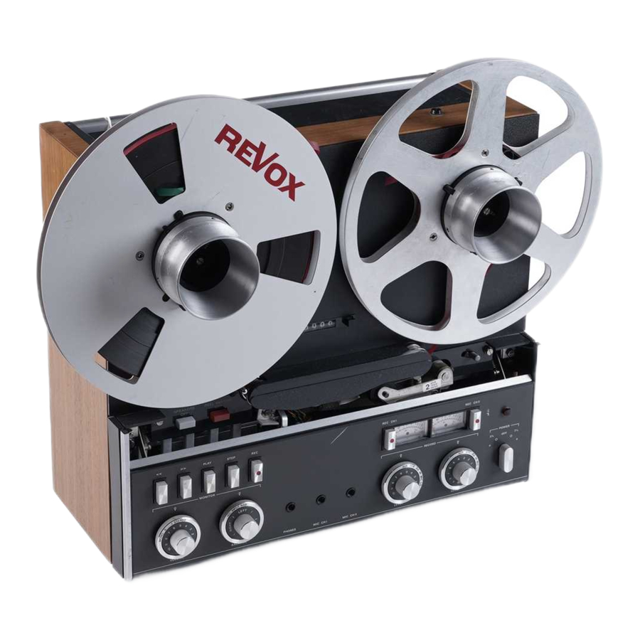
Revox A77 Manual
- Service manual (134 pages) ,
- Operating instructions manual (56 pages) ,
- Operating lnstructions (31 pages)
Advertisement
- 1 About Revox A77 and info on Mark versions
- 2 Necessary repairs and attention points
- 3 Location of the boards
- 4 Power supply PCB voltages
- 5 Power Supply Board layout
- 6 Tape Drive / Transport Control Board layout
- 7 Capstan Speed Control Board layout
- 8 Switch Board layout
- 9 VU-Meter Board layout
- 10 Backside connections
- 11 Front panel knobs layout
- 12 Calibration pots location
- 13 Quick Overview Of Electrical Adjustments /Alignment / Calibration
- 14 Documents / Resources
About Revox A77 and info on Mark versions
- All Revox A77's that have not been serviced will need service. These decks have been manufacured between 1967 and 1976, so by now they will probably be 50 years or older.
- There is a lot of experience in the field about what components have often failed, and what components will likely fail on your deck in the future if they still have not failed yet. So you should replace them now. This document is a breakdown of what to do to get a Revox A77 back into shape.
- For this you will need to take the deck apart, to the individual circuit boards. A lot of soldering and desoldering will be required, so experience in the repair field is recommended.
- This guide is NOT a tutorial, nor a guide to repair, but a Quick Reference Guide for technicians to get to information quickly, without having to search through the 300 page Service Manual back and forth all the time. But, the original SM is still required for reference and for specific problems, of course.
- As there a 4 versions of the A77, Mark I to Mark IV, there may be differences in your deck. This QRG focusses on Marks III & IV.
- How do you know which version you have?
- A77 - version MK I Serial-No. S 054 - S18 080 produced 08.1967 to 06.1969 Serial-No. G 100 - G 19 368 produced 10.1967 to 06.1969
- non spring left tapeguide, left roller is not a bearing but solid alu disc
- silver lower front, black vu meters that are only lit when recording
- dark shiny upper front
- plastic reeltables
- Revox logo with High Fidelity
- black and red plastic pushbuttons
- knobs transparent plastic
- A77 - version MK II Serial-No. S 18 081 - S 31 000 produced 06.1969 to 06.1970 Serial-No. G 19 369 - G 54 600 produced 06.1969 to 08.1971
- left tape guide spring loaded, left roller is bearing
- silver lower front, black vu meters that are only lit when recording
- dark shiny upper front
- alu reeltables
- Revox logo with High Fidelity
- black and red plastic pushbuttons
- knobs transparent plastic
- A77 - version MK III Serial-No. S 45 640 - S 72 852 produced 08.1971 to 08.1973 Serial-No. G 55 000 - G 145 099 produced 08.1971 to 08.1974
- dark lower front, silvery vumeters
- dark matte upper front
- single Revox logo
- black and red plastic pushbuttons
- knobs transparent plastic
- 3e lightbulb installed for meter illumination
- new chassis, is exchangeable
- pertinax pcb
- A77 - version MK IV Serial-No. G 145 100 - G 289 836 produced 08.1974 – 10.1977
- dark lower front, silvery vumeters
- dark matte upper front
- blue Revox logo with text "A 77 - STEREO - TAPERECORDER"
- revised controls in alu-look
- revised capstan PCB with IC 555 timer IC
- tape counter with gear and toothed belt
- epoxy pcb
- remark: the "S" at the beginning of the serial No. means "Made in Schwitzerland" a "G" means "Made in Germany"
- http://www.theimann.com/Analog/A77/Versionen.html
Necessary repairs and attention points
Here is the list of the necessary things to do:
- Before power on:
Replace the 4 rifa caps (0,47 µF = 470 nF) sparkkillers:- 3x on tape drive transport control board.
- 1x on capstan board.
- And if there are blown rifa's, check surrounding diodes and resistors.
- Set deck for 240 V operation (when in EU). Deck can now be switched on for testing.
- After power on, check on the power supply board:
- 21 V AD1 (red) & ED1 (yellow). Adjust P106.
- 27 V DM1 (blk) & DB1 (vio) & DF1 (vio) & DM2 (wht). No adjust possible.
- Then replace all electrolytic caps on the 7 audio cards, the switch board and the 3 control boards as well. A list is supplied further in this document. Probably replace tantalum too.
- Replace 3 rectifiers on Power Supply Board and Capstan Board.
- Replace motor caps 3x.
- Replace all 14x trimpots on the audio cards, 1x on the switch board, 1x on Power Supply Board, 1x on Capstan Board.
- Replace 4x SKF 608 (2Z or ZZ) bearings in both spoolmotors if noisy.
- Replace 1x SKF 626 (2Z or ZZ) tape guide bearing left side.
- Replace 3 caps on the switch board, and one trimpot.
There are also points of attention:
- The A77 won't latch if the remote plug on the top isn't installed
- The A77 won't turn on if the 2 plugs in the back near the powerplug aren't fitted. But be careful! They carry mains voltage.
- Clean the contact patches of the open switch on the switch pcb, which is connected to the power switch knob.
- Clean the open record switches next to VU meters for oxidation.
- Glue the VU meter needles to the base inside the meter (very difficult!! Only try when experienced. VU meter could get ruined).
- Check counter belt, replace if necessary. Lubricate the mechanism.
- Check counter workings.
- Check pinch roller, replace if necessary.
- Originally, in the A77 the left guide is abearing and the right guide is stationary. Sometimes it has been altered.
Location of the boards

Power supply PCB voltages

Power Supply Board layout

- Replace bridge rectifier D101 with new one (> 400 V 1,5 A)
for instance 2W04G-E4/51 - Replace 2 caps:
1000 µF / 40 V
2200 µF / 40 V - Replace trimpot 2,5 kΩ
- Don't forget the thin black wire at the back of the pcb!
Tape Drive / Transport Control Board layout
some values can vary between different versions
Relay A: Playback
Relay B: Rewind
Relay C: Fast Forward (+ Playback for ½ second)

- Replace 3 sparkkillers 470nF/>300V
- Replace C111 470µF/40V
Capstan Speed Control Board layout

- Replace bridge rectifier D101 with new one (> 400 V 1,5 A)
for instance 2W04G-E4/51 - Replace 5 caps:
10 µF / 63 V
22 µF / 40 V (2X)
220 µF / 6 V
220 µF / 25 V ax. - Replace trimpot P201 2,5 kΩ
Switch Board layout

VU-Meter Board layout

Backside connections

Front panel knobs layout
When all knobs and the face plate are off.... Now you know what you are doing There are 2 versions!!

Calibration pots location

Quick Overview Of Electrical Adjustments /Alignment / Calibration
Only IF you're familiar with the procedure (if not, I suggest you do it from Service Manual 1st time).
[stereo+max, NAB, aux+min, 2xrec] defines the knobs and buttons from left to right before each step.
0 - Demagnitise the heads and the complete tapepath.
1a - Capstan speed: check for 35..50 mV @ 9,5 cm/s at E1 (brown) and E2 (blue) of tacho head on capstan board.
1b – check for 1600 Hz / 19 cm/s at same terminals, adjust T201.
1c - check for 800 Hz / 9,5 cm/s at same terminals, adjust P201.
2 – check for 21 V AD1 (red) & ED1 (yellow) at power supply board. Adjust P106.
3 – Balance: [stereo+max, input, aux+max, 2xrec] supply 30 mV@1000 Hz at AUX inputs, and short the L/R input connectors. Adjust balance for ~2 V @ outputs equally L/R. Do not adjust the balance control from here on!
4 – Azimuth: adjust screw top-right of playback head playing azimuth calibration tape.
5 – Output: [I/II+max, NAB, aux+min] Play calibration tape, level section: set playback switch to 6.3.3 CH1/2, adjust REPR LEVEL 1/2 trimpot for 2 V at output.
6 - Frequency: [I/II+max, NAB] Play calibration tape, frequency section (-20 dB!): measure both 6.3.4 channels by changing switch to CH1/2, measure range 300 mV. (AFAIK nothing can be set).
7a –??Oscillator: [stereo+max, NAB, aux+min, 2xrec] Load test tape and record. Press both rec 6.4.1 buttons, Check VU board orange HB3 (CH2) & blue HB6 (CH1) for: 21 Vac for 2 track machines, 16 Vac for 4 track machines.
7b – Check oscillator frequency: 120 kHz ± 5 kHz at same terminals against ground. (No adjust)
8 - Bias Trap: [stereo+max, NAB, aux+min, 2xrec] Load test tape and record. Adjust Record Bias 6.4.3 Trap (5th/bottom trimpot!) for minimal voltage at test points C515 on both record amp pcbs for < 300 mV.
9 - Set Playback Bias Trap (2nd/bottom trimpot!) at playback amp cards to minimal voltage at 6.4.4 OUTPUT terminals. < 50 mV
10 - Record: [stereo+max, input, aux+max, 2xrec] Input ~3-4 mV @ 1000 Hz, adjust frequency 6.5 generator level for 200 mV @ OUTPUT
11 - Azimuth: record 10 kHz tone and adjust screw at top-right of rec head for maximum signal. 6.5.1 (or use XY-method)
12 - RF BIAS: input 10 kHz -20 dB, and adjust OSCILLATOR pots CLOCKWISE for both channels and 6.5.2 for both speeds (so 4x adjustment) to reach overbias after peak value at OUTPUT. ΔV = ~4 to ~5 dB overbias.
13 - repeat the previous azimuth setting.
14 - Record Level: [chI/II+max, input, aux+max, 2xrec] Short both AUX inputs. Record 1 kHz and 6.5.4 Before-and-after-tape switch to INP. Adjust generator so that OUTPUT is 200 mV.
15 - Switch to NAB and adjust REC LEVEL I/II trimpots for 200 mV @ OUTPUT. Playback mode 6.5.4 switch to CH1 or CH2 respectively.
16 - Record Equalization: Switch generator to 12 kHz -20 dB. Set to NAB. Adjust output voltage 6.5.5 between 0 to +1 dB with trimpots EQUALIZ. 0 dB = 200 mV @ 1 kHz. CH1 / CH2 & both speeds.
17 - Distortion: [chI/II+max, NAB, aux+max, 2xrec] 500 Hz @ 40 mV at INPUT. RECORD and measure 6.6.1 distortion. Set input level so that distortion < 2% at 19 cm/s 1
8 - VU Meter calibration see the SM. And good luck!
The rest of the SM is all checks but nothing that can be adjusted.
Documents / Resources
References
Download manual
Here you can download full pdf version of manual, it may contain additional safety instructions, warranty information, FCC rules, etc.
Advertisement


Need help?
Do you have a question about the A77 and is the answer not in the manual?
Questions and answers