Advertisement
Quick Links
ASSEMBLY INSTRUCTIONS
Before You Begin:Phillips screwdriver required for assembly (Not Included).
Please identify all component parts and hardware pieces required before you begin. Carefully remove all of the
components from the packaging and set aside for assembly. Assemble on a soft surface to prevent scratching during
assembly.
Tighten all components securely before use. Failure to do so may result in personal injury.
DO NOT use any sharp objects to open plastic wrapped components as damage to product or components may result.
CHOKING HAZARD - Small Parts. Adult Assembly Required.
DO NOT ALLOW CHILDREN TO CLIMB ON FURNITURE
Serious or fatal injuries can occur from furniture tipping over. You must install Tipping Restraint Hardware (where
included) to help prevent the unit from tipping and causing accidental injury, instability, death or damage. The tipping
restraint is intended only as a safety measure, it is not a substitute for proper adult supervision.
To help prevent furniture from tipping over it must be permanently attached to the wall. Anti-Tip Safety Wall Straps
suitable for the unit weight and wall materials (if not included) should be purchased and installed.
Customer Service Email: customerexperience@theubiquegroup.com | Phone:866-552-2810
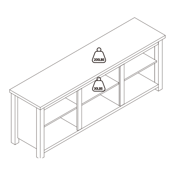
200LBS
30LBS
889142975946/889142975939/196861167782
Thank you for your purchase!
6 Cubby 65" TV Stand
for up to 80" TV's
Advertisement

Related Manuals for Ubique 6 Cubby


Summary of Contents for Ubique 6 Cubby
- Page 1 Thank you for your purchase! 200LBS 6 Cubby 65" TV Stand for up to 80" TV's 30LBS ASSEMBLY INSTRUCTIONS Before You Begin:Phillips screwdriver required for assembly (Not Included). Please identify all component parts and hardware pieces required before you begin. Carefully remove all of the components from the packaging and set aside for assembly.
- Page 2 Congratulations! You just purchased a piece of happiness. At Ubique Group, we believe you can transform your spaces into the most inspired places with furnishings that are the perfect combination of form, function and style. As original innovators of online furniture retail, we offer the best selection of popular, contemporary styles at cool, comfortable prices.
- Page 3 ASAP. But despite our best efforts, sometimes "slips happen." If you need any support, from replacement parts to recommendations, please reach out to our wonderful customer support team at 866-552- 2810 or customerexperience@theubiquegroup.com. We're here to help! EVERY UBIQUE GROUP PRODUCT Quality & Packaged Shipped from with Care our U.S.
- Page 4 PARTS 3.5*14 Screws Left Front Fascia Top Plate (1) (11) 12+1 3.5*20 Right Front Fascia Back Panel Screws Bottom Plate (2) (12) Left Rear Fascia Left Side Panel Shelf Holders (3) (13) Bottom Support Feet Right Rear Fascia Right Side Panel (4)...
- Page 5 STEP 1 Screw-In Pegs B*32 Dowel Pegs A*18 Right Inner Support Fascia (6) Left Inner Support Fascia (7) (1) Top Plate (5) *2 Front Upper Brace Inner Supports (8) (2) Bottom Plate (12) Right Front Fascia (4) Right Side Panel (14)...
- Page 6 STEP 3 Female Camlock Screw-In Peg (13) Receiver Hole Left Rear Fascia Left Side Panel (3) Ensure groove opening faces upwards (11) Left Front Fascia Receiver Hole STEP 4 3.5 Screws Bottom Support Feet STEP 4: Attach Bottom Support Feet (Part H) to the underside of Bottom Plate (Part 2) using (8) 3.5 Screws (Part E).
- Page 7 STEP 5 (4) Grooves (8) (8) Upper Front Panel (2) STEP 5: Insert Female Camlocks (Part C) into the Upper Front Panel (Part 8) and ensure the arrow side is facing outwards. Slide the Screw-In Pegs on the Left and Right Side Panels into the Female Camlock Receiver Holes in the Bottom Plate and Upper Front (3)...
- Page 8 STEP 7 STEP 7: Ensure Female Camlocks (Part C) are inserted in holes with open side facing outwards toward receiver hole for Screw-In pegs (Arrow Side). Slide Inner Supports (Part5) onto Screw-In Pegs on the bottom plate. Turn the Female Camlocks (Part C) clockwise to tighten.
- Page 9 STEP 9 (6) (7) Right Fascia STEP 9: Insert Female Camlocks (Part C) into holes with arrow side pointing outwards. Insert preassembled Screw-In Pegs on Left Fascia (Part 7) and Right Fascia (Part 6) into Left Fascia the Receiver Holes and turn Female Camlocks clockwise to tighten.
- Page 10 STEP 11 G*12 Shelf Holders (16) Right Shelf (15) Middle Shelf (16) Left Shelf STEP 11: Insert Shelf Holders (Part G) into holes at the desired height then place the Left & Right Shelves (Part 16) and the Middle Shelf (Part 15) onto Shelf Holders.
- Page 11 Quality and Safety Guidelines: Please follow the static and dynamic weight capacity limits provided on this item. If you are unsure of the weight capacities for this product, email us at customerexperience@theubiquegroup.com or call 866-552-2810. Please use this item on a stable, level surface only. All TV Stand legs/feet should contact the flooring surface when in use.
Need help?
Do you have a question about the 6 Cubby and is the answer not in the manual?
Questions and answers