Advertisement
Introduction
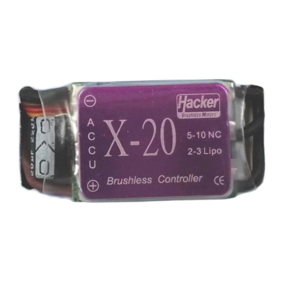
X- Series Controller - a new generation of sensorless speed controllers especially for 'Hacker Brushless A Series Motors' and other Brushless Motor Designs. Special programming options are provided to ensure the best possible power and performance from your motor system. 'Brushless' systems offer high power efficiency combined with low weight and compact dimensions. For best performance and reliability from your Controller, use only High quality connectors, motors and batteries.
Please, pay careful attention to the following instructions before you start to work with your new motor and speed controller.
The speed controller can be connected to the motor by direct soldering or with high quality connectors. Always use new connectors, which should be soldered carefully to the cables and insulated with Heat-shrink tubing. It is possible to extend the cables to the motor battery pack up to a maximum of 8 inches. Deans Ultra or other high quality connectors are recommended for connecting the motor battery pack to the controller.
- Solder Controller to the Motor wires
- Solder appropriate connectors to the Battery wires
- Insulate all Solder connections with Heat Shrink Tubing.
- Plug the JR connector into the receiver throttle channel.
When connecting controller to battery pack, care should be taken to ensure that multiple touches of the connectors are not made.
Installing the Controller
Install the speed controller in the model so that it is isolated from vibration and shock, using Velcro or double sided foam tape. Allow space around it for cooling. Make sure that there is sufficient cooling of the motor and speed controller by ducting air through adequate cooling holes from the outside airflow. Main power packs should be connected at one attempt.
The X-speed controllers have an optimal default setup for A Series Motors.
Factory default settings
Brake: Off
Battery type: 3 Li-Poly (ca. 7,8V)
Under voltage: Reduce power
Acceleration : delayed
Timing: Auto
Frequency: 8KHz
Normal start up:
When throttle stick is off, connect battery pack, and you will hear one beep for Brake on or two tones for Brake off.
For changing the default setup, please read the following manual
ESC program procedure
Program mode
X-7, X-12, X-20, X-30- With throttle stick at full power, connect the battery and wait for 5 sec. Program mode is entered when you hear two low tones and two high tones. _ _ - - Each time you enter the programming mode you are allowed to make one change and then you will automatically exit the programming mode. To change more than one parameter you will have to re-connect the battery and re-enter the programming mode each time.
X-40- With throttle stick at full power, the ESC switch must be in the on position, connect the battery and wait for 5 sec. Program mode is entered when you hear two low tones and two high tones. _ _ - - Each time you enter the programming mode you are allowed to make one change and then you will automatically exit the programming mode. To change more than one parameter you will have to re-connect the battery and re-enter the programming mode each time.
- Brake
To change the brake function, as soon as you hear the programming tones mentioned above, move the throttle stick to low position. Brake function will be inverted. (IE: If brake was on, it now will be off.)
To change any of the remaining functions, enter the programming mode as detailed above. Leave the throttle at high position until you are within the five sets of beeps as detailed in each of the choices below. When you arrive at the choice you want to make, move the throttle to low position while that series of 5 tones are still being heard. - Battery type
Voltage Cut-off)
NiCad:
. . . . .
2 Lipos: (5.8V)
.. .. .. .. .. ..
3 Lipos: (7.8V)
... ... ... ... ... - Under voltage
reduces power when the battery gets low.
![]()
cuts off power when the battery gets low.
![]()
- Acceleration
Fast:
V V V V V
Delayed:
VV VV VV VV VV - Timing
Automatic: (7 ~ 30 degree) (recommended)
- - - - -
Soft: (7 degree) (2-pole motors)
-- -- -- -- --
Hard (22 ~ 30 degree) (multipole motors)
--- --- --- --- --- - Frequency
8 kHz: (recommended)
\ \ \ \ \
16 kHz
/ / / / / - Rotation reverse
Reverse motor rotation
W W W W W


Trouble shooting
- Switch "ON" the transmitter and check the throttle channel settings are +/-100% (for computer radios). For Futaba Radios program the "Servo Reverse" function on the throttle channel. Set the throttle to "closed" or brake position
- Locate the controller to Avoid multiple touches of the connectors when installing a fresh motor battery pack
- You must hear a 'beep'. Between switching on the switch and the 'beep' the throttle stick must not be moved. If you do not hear a 'beep', switch off the switch, disconnect the power connectors, wait for 5 seconds and repeat the procedure of connecting and switching on.
- If you do not hear 'beep' again, check the following:
- Is JR connector plugged in throttle channel?
- Is the throttle stick in "closed" position (OFF)?
- Is the throttle channel in 'normal' position? (for Futaba, in the Reverse position?)
- The position of 'full throttle' will be adjusted automatically
- All programming will be stored.
- Reversing the motor directions is achieved by the exchanging the position of any two wires connected to the motor.
- The speed controller will turn-off the motor when the main power pack voltage falls under 5,8 V. It depends on which occurs first.
- Temperature overload protection is built into the speed controller; it turns off the motor when the temperature reaches 230º F /110º C.
- These speed controllers are equipped with protection functions that take care of correct start and operation of the motor across the whole range of RPM, Current and Voltage.
- Do Not connect the speed controller to just 'any' kind of power source. Take care to ensure the right polarity of NiCd/ NiMH or LiPoly power packs only.
- Do not connect the motor battery to the wrong polarity; the speed controller will be severely damaged.
- Controllers connected to the wrong battery polarity, WILL NOT be covered under the warranty
Technical and Electrical Data
| Type of esc | Dimensions | Weight | Operating range | Operating current | BEC load |
| X-7 | 29x23x9mm | 10g (0.36oz) | 2-3 LiPo/510NC | 7A | 2-3 Servos |
| X-12 | 42x24x9mm | 15g (0.53oz) | 2-3 LiPo/510NC | 12A | 2-3 Servos |
| X-20 | 42x24x9mm | 16g (0.57oz) | 2-3 LiPo/510NC | 20A | 2-4 Servos |
| X-30 | 51x24x10mm | 24g (0.85oz) | 2-3 LiPo/510NC | 30A | 2-4 Servos |
| X-40 | 81x28x10mm | 45g (1.6oz) | 2-3 LiPo/510NC | 40A | 2-4 Servos |
Sensorless speed controllers especially for 'Hacker Brushless A Series Motors'.
The special programming options are provided to ensure the best possible power and performance from your motor system also for other Brushless Motor Designs.

- Once the Motor Battery Pack is connected, handle the model with extreme care! Ensure that you are well clear of the propeller at all times. Rotating propellers are extremely dangerous!
- Always connect the motor battery pack just before flight and disconnect it immediately after landing the model.
![]()
Even when the switch is 'off' remember the Motor Battery pack may be connected, handle the model with extreme care and stay well clear of the Propeller!
Tel.: 0049 (0) 8761-752 129
Fax.:0049 (0) 8761-754 314
E-MAIL: info@hacker-motor.com
Documents / ResourcesDownload manual
Here you can download full pdf version of manual, it may contain additional safety instructions, warranty information, FCC rules, etc.
Download Hacker X Series, X-7, X-12, X-20, X-30, X-40 Manual
Advertisement


Need help?
Do you have a question about the X Series and is the answer not in the manual?
Questions and answers