Advertisement
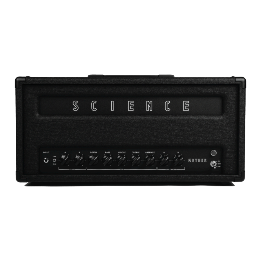
Front Panel
Input Jack: Standard 1/4" mono input for your guitar or bass.
Gain A: Controls the overall gain of Channel A, ranging from clean to crunch.
Gain B: Wide range gain control that spans from edge-of-breakup, to crunch, to heavy overdrive in the last ⅓ of its rotation.
Depth: 4-way rotary switch that adjusts the overall low-end depth and low-midrange of the preamp. Position 1 (most counter-clockwise) provides the tightest low-end, great for neck pickups, down-tuning, or a more focused lean tone. Position 2 adds low-midrange, but keeps the low-end tighter like Position 1. This warms up clean sounds and thickens overdriven sounds. Position 3 adds deep bass, but keeps the low midrange clearer. Position 4 (most clockwise) adds additional low-midrange in addition to deep bass, which provides the thickest tone available. While using positions 3 and 4 at higher gain settings the overdrive will take on a fuzzier quality.
An easier way to remember the settings:
- Tight,
- Tight + Low-mid,
- Deep,
- Deep 3 + Low-mid
Bass: Adds bass frequencies to both channels when turned clockwise, and reduces bass when turned counter-clockwise.
Middle: Adds mid-range frequencies to both channels when turned clockwise, and reduces mid-range when turned counter-clockwise.
Treble: Adds treble frequencies to both channels when turned clockwise, and reduces treble when turned counter-clockwise.
Absence: Turn clockwise to smooth out the upper harmonics, especially in distorted sounds, and turn counter-clockwise to bring the sound forward and add top-end and bite.
Loudness A: Adjusts the overall volume of Channel A.
Loudness B: Adjusts the overall volume of Channel B.
OFF/ STBY (Standby) /ON Switch: 3-Way switch. Down is OFF, middle is Standby, and up is ON.
About Standby: Standby mode mutes the sound and allows the tubes to heat up before applying high voltage to the amp when turned ON. Leave in Standby for 30 seconds to a 1 minute before switching ON. Standby mode can also be used to mute the amplifier while leaving the tubes warm for short breaks. For long breaks, however, it is best to turn the amplifier completely OFF.
To turn the amplifier OFF, follow the same turn-on procedure – but in reverse order – allowing the amp to idle in Standby for about 30 seconds before powering down. While it is perfectly okay to turn the amp OFF immediately, idling in standby before powering down lets the filter capacitors inside the amp fully discharge. If turned OFF immediately, the amp will switch back to Channel B by default (if it's not already on Channel B), and there will still be some sound as the filter caps continue to discharge, which may be annoying or jarring.
Note: Amps fitted with the Ghost Effects Loop will experience a short delay when switching from Standby to ON. This is normal.
Indicator lamp: Attractive red neon light to indicate the amp is ON.
Rear Panel

Use with a grounded power outlet only! Discard the power cord immediately if the ground pin is damaged/broken. The ground connection is for your safety in the event of a fault condition!
Main AC power inlet: Plug in the included standard IEC power cord here. Mains input voltage is marked under the mains AC inlet.
Only remove and change fuses with the amplifier unplugged from the outlet!
Your amp is fitted with fuses for safety as well as protection for the amplifier's most expensive components. Fuses are user-replaceable, and if a fuse does need changing, always replace it with the correct type and rating (as designated on the rear panel of the amplifier).
To check if a fuse is blown, turn the amplifier OFF and remove the IEC cable. Push and twist the spring-loaded fuse holder counter-clockwise to remove the fuse. Look inside the glass to see if the small wire inside the glass is broken. Additionally, there may also be a burnt looking area on the inside of the glass. You can also check with a digital multimeter set to the lowest Ohms settings. The fuse should read close to 0 Ohms if still intact.
If you replace a fuse and it blows again, there is likely a more serious problem. Please contact us (info@scienceamps.com) before replacing the fuse a second time so that we can further assist you with the trouble-shooting.
Mains Fuse: 1 ¼" x ¼", Slow Blow, 250V glass cartridge fuse. This fuse is fitted for safety, but can still blow under some normal amp fault conditions. If the indicator lamp does not come on, then it is likely the Mains Fuse has blown (otherwise the lamp itself has burned out).
HT Fuse: 1 ¼" x ¼", Slow Blow, 250V glass cartridge fuse. If the amp's main indicator lamp is still illuminated, but produces no sound at all then it's most likely the HT Fuse has blown. The most common reason for this is a faulty output tube.
Speaker Jacks and Impedance Selector
Note: Speakers must be rated for at least the full rated clean output power of the amplifier (50W, 100W, or 200W depending on your model). When overdriven, the rated clean power can be exceeded by tens of watts, and therefore it is preferable to use speakers that have a combined power rating which exceeds the clean power rating. This topic is up for debate as some speaker manufacturers rate their speakers with this in mind (i.e. four 25W rated speakers may be OK for a 100W amp), however better safe than sorry is a good approach when it comes to expensive speakers.

Always verify a speaker cabinet's impedance before connecting it to the amplifier's speaker outputs. An impedance mismatch can potentially damage the amplifier and is not covered under warranty.
- When using one speaker cabinet: With the amp OFF, plug in a speaker cabinet to either Speaker Output jack using a quality ¼" speaker cable.
When using two speaker cabinets: When using two speaker cabinets, both must be the same impedance (i.e. two 8 ohm cabs), and the impedance selector should be set for half each cab's impedance. For example: - When using two 8 ohm cabs: Set the impedance selector should be set to 4 ohms.
- When using two 16 ohm cabs: Set the impedance selector should be set to 8 ohms.
- When using two 4 ohms cabs: This configuration is not supported with the stock output transformer, and would require a custom 2 Ohm tap.
Footswitch Jack
¼" jack for the included footswitch. Connect with a typical ¼" instrument cable. The footswitch toggles between Channels A & B. When the LED is off, Channel A is active; when the LED is illuminated, Channel B is active.
Ghost Effects Loop
(optional)
The Ghost Effects Loop is a ultra-transparent serial effects loop designed to work with instrument level effects (i.e. effects pedals) and some line level equipment (i.e rack effects units). In general, time-based effects such as reverb and delay are typically placed in the effects loop. The effects loop is located after the preamp section of the amp, where most of the overdrive/distorted tone is generated. Placing time-based effects pedals or processors in the loop allows their effect to be heard more clearly. For example, if the amp is set to be overdriven, an effect like delay or reverb going into the amp's input will be overdriven, causing them to become washed-out and distorted. Conversely, inserting effects like delay and reverb in the amp's effects loop will allow you to effect your already overdriven sound, producing a clearer effect. That said, there is no correct way to use your effects, and it's all a matter of taste/preference, so experimentation is key!
Note: The Return jack of the Effects Loop may also be used as a power amp input, and in conjunction with a separate preamp device. When used in this way, only the Absence control will be active, and the overall voicing of the power amp will affect the sound. This may sound great, but should be noted the EQ response of the power amp is not "flat" when using the effects loop Return as a power amp input.
Tip: A volume pedal also works well in the effects loop, acting as an overall master volume, which can be extremely useful in a live setting, however a buffered pedal is preferred to prevent treble loss.
Send Jack: Connect to the input of your effects via ¼" shielded instrument cable.
Return Jack: Connect to the output of your effects via ¼" shielded instrument cable.
Tip: The effects loop interfaces your amp with the "outside world", and sending the sensitive audio signal out to your pedal board and back is no small task! The effects loop is buffered (and hopefully the last pedal in your chain is too) making it less susceptible to noise interference, the send and return cable specifically are prone to noise pickup. Because of this, experiment with physical send and return cable routing. In general, running cables around the input jack side of the amp is preferable since it's furthest away from the amp's power transformer.
Tube Life & Biasing
Tubes can become extremely hot during normal operation. Make sure the amplifier is OFF, and always allow tubes to cool before handling to prevent burns.
Preamp Tubes
Preamp tubes typically last many years, but fail occasionally. Typically they will become noisy or "microphonic" before they degrade your amplifier's sonics. This is characterized by ringing, static, or popping noises.
Changing Preamp Tubes:
V1, V2, V3, V4 (100 & 200W version only, see tube diagram)
To remove tubes, gently pull upward using a very slight circular motion if necessary. When re-inserting a preamp tube, mind the pin/socket orientation as they are "keyed" to insure proper installation.
Output Tubes
Output tubes (See tube diagram) generally produce a strong output for 6 months to a year when played regularly, then they may become dull sounding, and/or the amplifier may begin to lose some power. Output tubes may last much longer depending on how hard the amp is played. Sometimes they die gracefully, but sometimes abruptly, causing a fuse to blow, which in turn protects the amplifier from further damage.
It's sometimes possible to see in plain sight which output tube(s) is (are) damaged. If necessary, remove the output tubes to inspect them, grabbing the plastic base and gently pulling up in a shallow circular motion.
Here are things to look for:
- The shiny silver area on top of the tube has turned white (the tube has lost vacuum).
- Burned spot(s) on the large gray structure inside the tube (the tube has "red-plated"/drawn excess current.
- Red silk-screened tube logo has become discolored (the tube has potentially overheated).
- The filament - part of the tube that glows) is not lighting up (not common, but can happen).
Like preamp tubes, sometimes output tubes can become "microphonic". This occurs when some internal part of the tube becomes physically loose, and in turn, the noise then gets amplified. The noise can be anything from static, a high-pitched ringing, or intermittent sputtering noises. This is usually exacerbated by vibration from the speaker cabinet. If you think a tube may be microphonic, try isolating the amplifier from the speaker cabinet to see if the noise stops.
Tip: If you think you have a microphonic tube, you can very gently tap on each tube with a pencil's eraser (a chopstick works well too) to see if the sound becomes worse, stops, or changes. All tubes will amplify the sound of the tapping a little, especially preamp tubes, but for example, if you hear an intermittent ringing sound and tap each tube to find V7 (for example) is causing the ringing to start/stop, you can be sure it's the problematic tube!
Note: Sometimes output tubes may rattle with vibration, which can be heard acoustically, but not through the speaker. This is relatively common in output tubes, especially after they have been subjected to vibration by the speaker cabinet or during transport. A rattling tube is not considered "microphonic" or problematic as any rattle is usually many decibels below the amplified sound.
Changing Output Tubes
V5, V6 and V7, V8 (100 & 200W version only)
Please see tube & bias diagram
In general, it's best to change all output tubes at once, and preferable to buy a "burned-in" matched set from a reputable dealer.
Output tubes can be replaced and biased easily by a qualified technician, however, if you would like to replace and bias the output tubes yourself, please read the detailed information about your amp's biasing system and procedure in the following sections.
Bias Control & Test Points
Every Science Amplifier comes equipped with user-accessible bias test points and bias control located on top of the chassis, adjacent to the output tubes. They can be accessed by removing the rear panel of the amplifier.
Please see the Tube & Bias Diagram to identify the controls and test points.
Bias Control: The bias control is a recessed slot adjustment (looks like a ¼" jack at first glance), which can be adjusted with a normal flathead screwdriver.
Test Points (for use with standard multimeter probes):
- Ground 1, Black: Plug in negative multimeter probe here while measuring bias for V5 and V6.
- V5, Red: Plug in positive multimeter probe to measure V5 output tube bias.
- V6, Red: Plug in positive multimeter probe to measure V6 output tube bias.
- Test points below are only fitted on 100W & 200W models:
- Ground 2, Black: Plug in negative multimeter probe here to check bias for V7 and V8.
- V7, Red: Plug in positive multimeter probe here to measure V7 output tube bias.
- V8, Red: Plug in positive multimeter probe to measure V8 output tube bias.
Bias Measuring & Biasing Procedure
What is bias?
Simply put, bias refers to the idle current flowing through the output tubes. In fact, all tubes need to bias, but in guitar amps the bias of the preamp tubes is permanently set and does not need adjustment. Here we will be only discussing the measurement and adjustment of the output tubes' bias current.
Maladjustment of the bias control can lead to output tube failure. The bias adjustment is not fool-proof, and output tubes can be under-biased (i.e. too "hot"). The bias control needs a wide enough range to accommodate different tube types and sets (tubes vary from set to set), and therefore it is possible to under-bias the output tubes in some cases. If under-biased for a sustained period, the output tubes will over-dissipate and likely fail. Science Amplification is not responsible for output tube failure due to maladjustment of the bias control.
Please familiarize yourself with the bias procedure before making bias adjustments. If you feel uncomfortable making adjustments, take the amp to a qualified technician. We do, however, encourage you to bias yourself. It is easy once you get the hang of it, and can save you some time and money!
Adjusting the bias requires the amplifier to be ON. The output tubes adjacent to the test points and adjustment control get very hot during normal operation and there is a potential burn hazard. Be careful near those hot tubes!
Here are some situations where you may need to check and/or adjust the bias:
- You are changing output tubes.
- You are changing output tube type from EL34 to 6L6 or vice versa (applies to 50W and 100W models only).
- The amp is quieter than normal/output power has decreased
- The amp has lost treble response
- The amp has a hum that is not affected by the setting of the Loudness control(s).
What you'll need:
- A #2 Phillips screwdriver to remove the amp's back panel.
- An electronic voltmeter (a digital model is preferred) with a millivolt setting. These can be found inexpensively and just about any one will do.
- A small flathead screwdriver to adjust the bias control.
- A speaker cabinet or load to plug into.
Biasing Procedure
(Please see the tube diagram)
Measuring & Adjusting Output Tube Bias:
- Use a #2 Phillips head screwdriver to remove the rear panel of the amplifier.
- With a speaker cabinet or load plugged in, turn the amp to Standby, let it warm up for about 1 minute, then turn ON.
- Set your multimeter to DC millivolts (mV).
- Insert the negative/common test probe into the black test point (ground). On 100W and 200W models use the black test point that is adjacent to the tubes you are measuring.
- Plug the positive probe into the red test point behind the tube you are measuring.
- Take note of the reading on the meter.
- Remove the probe from the red test point, and repeat the procedure for each tube. On 100W and 200W models, move the negative probe to the other black test point nearest the tubes you are measuring.
Your readings should be within 10 millivolts of each other, which means the tubes are reasonably matched. If a reading on a particular tube is below the safe/suggested ranges (see below) by more than 10-15mV, then it's possible a tube has gone bad and needs to be replaced. - Here are the bias settings/ranges for each tube type and model. Biasing on the lower, "cooler" side will slightly increase headroom and tube life. Biasing higher, or "hotter" will encourage quicker power tube distortion, but slightly decrease tube life. These differences are very subtle, however.
- 50W & 100W model:
EL34: 30mV to 40mV
6L6: 36mV to 46mV - 200W model:
KT88: 25mV to 35mV
- 50W & 100W model:
- If adjustment is necessary, turn the bias control with the small flathead screwdriver while monitoring the number on the multimeter to obtain the desired setting.
Changing Output Tubes:
- Turn the amplifier OFF and wait for tubes to fully cool. To remove, gently grab the plastic or metal base and pull upwards, using a very slight circular motion if necessary.
- Insert the new tubes, minding the "key" on the bottom of each tube so that it matches with the socket.
- Turn the bias control to minimum (all the way counter-clockwise).
- Follow steps 2-7 from the "Measuring & Adjusting Output Tube Bias" instructions above.
- Turn the bias control clockwise with a small screwdriver until you reach the desired bias setting listed above and also on the Tube Chart & Bias Diagram.
- Allow tubes to idle for 15 minutes, then recheck bias and adjust if necessary.
Care and Maintenance
Do not use household cleaning products. If control panels need cleaning, use only a soft clean dry or damp cloth to wipe off smudges. To clean tolex, wipe with a damp cloth and allow to dry before operating.
Periodically check the 4 mounting screws on the bottom to ensure they are tightened. These screws secure the chassis to the head cabinet, and also insure contact to the aluminum RF shielding plate inside the cabinet. If possible, move the amplifier when the tubes have had the chance to cool down for a few minutes. Because the tubes get very hot, the elements inside become more vulnerable to physical damage until the tubes have cooled. So in general, try to move the amp off stage last after you have packed up other equipment.
Tube & Bias Diagram

Birds-eye view of the Mother's tube layout and bias controls
Safety
- Always use a 3-prong cable into a grounded outlet. This makes sure the amplifier is always grounded and safe during the rare occurrence the chassis should become "live" (electrified).
- Only change fuses with the amp unplugged from the outlet!
- Only replace fuses with the same type and rating!
- Tubes become very hot during normal operation. Allow them to cool before handling to prevent burns.
- Never change tubes with the amplifier ON.
- Always make sure the amp's vents are open, allowing heat to escape and air to flow freely.
- Keep the amp away from moisture, and never put any beverages on top of the amplifier, no matter how convenient it may seem!
- There are potentially lethal voltages present inside the amplifier. Do not open the amplifier chassis unless authorized and are a qualified technician.
Documents / ResourcesDownload manual
Here you can download full pdf version of manual, it may contain additional safety instructions, warranty information, FCC rules, etc.
Advertisement

Need help?
Do you have a question about the MOTHER and is the answer not in the manual?
Questions and answers