Adcom GFA-555 PRO, GFA-555 Manual
- Owner's manual (11 pages) ,
- Owner's manual (10 pages) ,
- Owner's manual (10 pages)
Advertisement
- 1 INTRODUCTION
- 2 WHAT TO DO WHEN YOU OPEN THE BOX
- 3 WHERE TO PUT IT AND WHERE NOT TO
- 4 WHERE AND HOW ALL THE WIRES GO
- 5 BRIDGED/MONO HOOK UP
- 6 UNIT PROTECTION CIRCUIT
- 7 SAFETY WARNNG
- 8 WHY WE BUILT IT THE WAY WE DID
- 9 THE CARE AND FEEDING OF YOUR PRODUCT
- 10 IF YOU HAVE A PROBLEM OR QUESTION
- 11 SPECIFICATIONS
- 12 Documents / Resources
INTRODUCTION
It is very important that you read this owners manual thoroughly before turning on your ADCOM GFA-555 Power Amplifier.
Your ADCOM GFA-555 represents the most advanced thinking in audio amplifier design. At 200 watts per channel, the GFA-555 offers an exceptional value; superior performance at a reasonable price. Some of the outstanding features of this product are:
- 200 Watts per Channel, 20Hz - 20KHz, into an 8 ohm load with both channels driven less than 0.09% Total Harmonic Distortion.
- 325 Watts per Channel, 20Hz - 20KHz, into a 4 ohm load with both channels driven with less than 0.25% Total Harmonic Distortion.
- The ability to drive very low impedance loads.
- Bridged mode power of 600 watts, 20Hz - 20 KHz, into an 8 ohm load with less than 0.25% Total Harmonic Distortion.
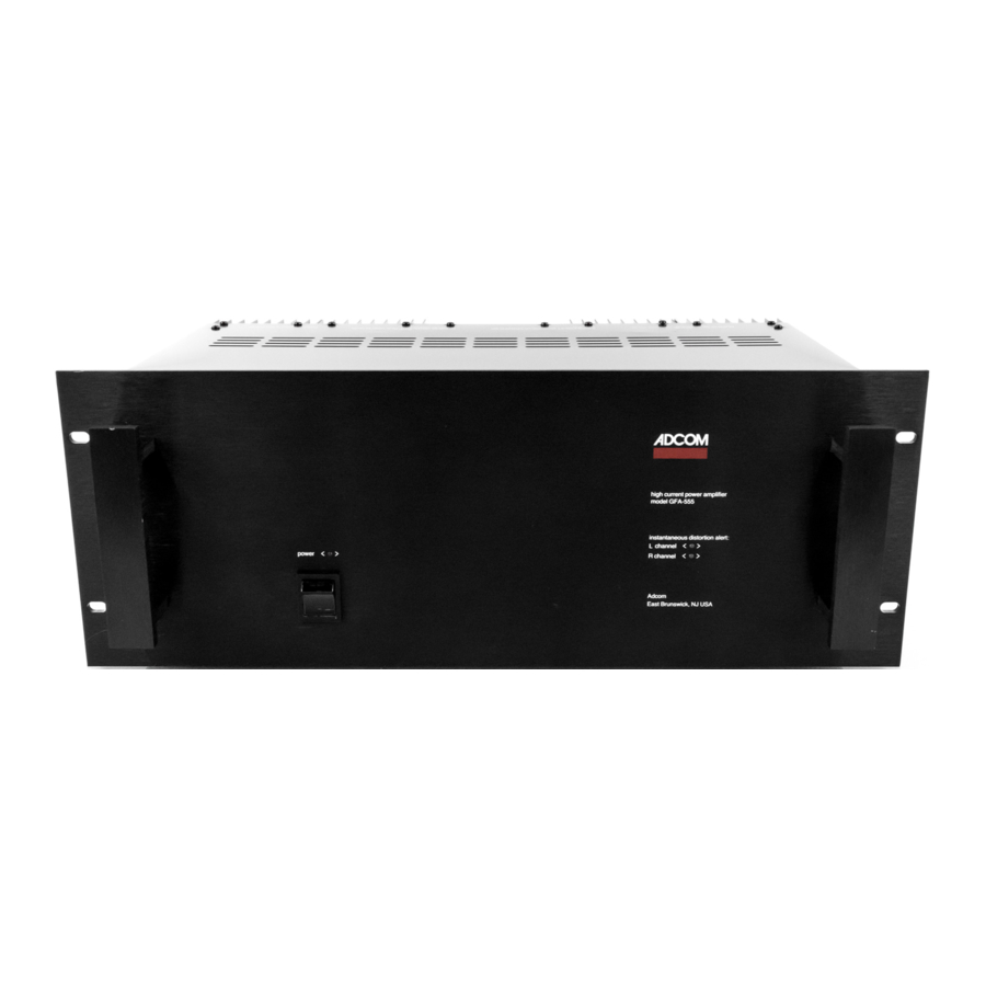
- Instantaneous Distortion Alert which indicates when distortion products are above the 1% level.
- Power supply circuit breakers for overload protection.
- Provisions for both Balanced and Unbalanced input signals.
This manual has been written to anticipate the kind of questions you may encounter while enjoying your GFA-555 power amplifier. Please read it thoroughly to fully understand all of the features offered and how they can be used to maximize the performance of your audio system.
WHAT TO DO WHEN YOU OPEN THE BOX
Before each GFA-555 left the factory, it was carefully inspected for physical imperfections as a routine part of ADCOM's systematic quality control. This along with full electrical testing, should insure a product flawless in both appearance and performance. After you have unpacked the amplifier, inspect it for physical damage. Save the shipping carton and all packing materials as they are essential to reduce to a minimum the possibility of transportation damage should the product ever need to be shipped again. In the unlikely event that damage has occurred, notify your dealer immediately and request the name of the carrier so that a written claim to cover shipping damage can be initiated.
THE RIGHT TO ANY CLAIM AGAINST A PUBLIC CARRIER CAN BE FORFEITED IF THE CARRIER IS NOT NOTIFIED PROMPTLY AND IF THE SHIPPING CARTON AND PACKING MATERIAL ARE NOT AVAILABLE FOR INSPECTION. SAVE ALL PACKING MATERIALS UNTIL THE CLAIM HAS BEEN SETTLED.
WHERE TO PUT IT AND WHERE NOT TO
The GFA-555 utilizes large external heat sinks to dissipate heat from the power transistors. The top and ![]() bottom panels of the amplifier have slots to allow air to circulate inside the amplifier. Adequate air circulation must be available to ensure cool operation of the amplifier. Therefore, the GFA-555 should not be completely enclosed with other heat producing components, and adequate space around the amplifier should be maintained. We recommend at least 3 inches on the top and 1 inch on the sides and rear for air circulation. If the GFA-555 is going to be mounted in an enclosed cabinet, it is recommended that the back of the cabinet have vents to allow air to circulate around the amplifier. With these considerations in mind, the GFA-555 should perform quite happily in any reasonable environment. Of course, such normal considerations as protection from excessive dust and moisture should always be observed. The ADCOM GFA-555 power amplifier has been carefully designed with high quality components so that long term undiminished performance may be expected from the amp when it is operated in accordance with the instructions provided.
bottom panels of the amplifier have slots to allow air to circulate inside the amplifier. Adequate air circulation must be available to ensure cool operation of the amplifier. Therefore, the GFA-555 should not be completely enclosed with other heat producing components, and adequate space around the amplifier should be maintained. We recommend at least 3 inches on the top and 1 inch on the sides and rear for air circulation. If the GFA-555 is going to be mounted in an enclosed cabinet, it is recommended that the back of the cabinet have vents to allow air to circulate around the amplifier. With these considerations in mind, the GFA-555 should perform quite happily in any reasonable environment. Of course, such normal considerations as protection from excessive dust and moisture should always be observed. The ADCOM GFA-555 power amplifier has been carefully designed with high quality components so that long term undiminished performance may be expected from the amp when it is operated in accordance with the instructions provided.
WHERE AND HOW ALL THE WIRES GO
All connections are conveniently located on the rear panel of the GFA-555 PRO. Any suitable program source; such as a control preamplifier or mixing board may be used. ALL CONNECTIONS MUST BE MADE WITH THE AMPLIFIER UNPLUGGED AND THE AC POWER SWITCH OFF.
Inputs are provided for both Balanced and Unbalanced input signals. There is a selector switch on the rear panel of the amplifier for Balanced and Unbalanced Input selection. The jacks provided for Unbalanced input signals are standard 2 conductor 1/4 inch phone type. The jacks provided for the Balanced input signals are for XLR connectors. Input signal attenuators are provided for matching left and right signal levels. These attenuators are mounted on the front panel for your convenience.
The Output terminals on the GFA.555 are the standard 5-way binding posts. The output terminals are spaced to permit the use of the so called "Banana Plugs" when using the amplifier as a stereo unit.
When connecting speakers to the GFA-555, you should always use the largest wire size (lowest gauge number) that is available to you. We recommend at least 16 gauge, 2-conductor cord (zip cord) for distances up to 25 feet. For distance up to 50 feet, 14 gauge wire should be used. You may also wish to consider some of the commercially available speaker cables which have been designed to improve the connection between the power amp and the speakers.
When connecting the speaker wires, correct phasing is required to obtain maximum bass response and to preserve a coherent sound when vocalists perform. The simplest way to insure proper phasing is to inspect the wires being used. Some form of coding is always employed, whether a ridge or groove on one edge or side of the wire, or the wires may be of different colors: one copper wire and one silver. For example, to connect a speaker to the Left Channel of the GFA-555 using a length of color coded wire, connect the copper colored wire to the Left Channel Positive (Red) output terminal on the amplifier. Next connect the silver colored wire to the Left Channel Negative (Black) output terminal. Now connect the other end of the copper colored wire to the Positive terminal of the Left speaker. Connect the other end of the silver colored wire to the Negative terminal of the Left speaker. Follow the same procedure for connecting the Right speaker to the Right channel outputs. IT IS IMPERATIVE THAT THE MAIN POWER TO THE AMPLIFIER IS DISCONNECTED DURING THE HOOK UP PROCEDURE.
The GFA-555 PRO has a detachable grounded AC line cord. This cord should be connected to the amplifier before pluggng the unit into the AC wali outlet. Remember, all input and output connections should be made before plugging the amplifier into the wall outlet. After the correct hook up procedure has been followed, the AC line cord should be plugged into an outlet providing 120 volts AC, 50/60 Hz.
BRIDGED/MONO HOOK UP
The ADCOM GFA-555 PRO amplifier can be used as an extlemely powerful monaural amplifler without the use of any additional accessories or modifications.
For mono operation, the Stereo/Bridged switch on the rear panel should be placed in the Bridged position. In the Bridged mode only a single input cable is used. The input cable to the GFA-555 should be plugged into the Right Channel input only. The Right Channel input signal attenuator will function should amplifier matching be necessary.
When connecting a single speaker to the GFA-555 in bridged operation, the Positive lead from the speaker should be connected to the Right Channel Positive (Red) output terminal on the GFA-555. The Negative lead from the speaker should be connected to the Left Channel Positive (Red) output terminal. Remember that when connecting the speaker wires, you should maintain proper phasing to obtain maximum bass response and coherent sound quality.
UNIT PROTECTION CIRCUIT
Your GFA-555 power amplifier is equipped with extemally mounted circuit breakers. These Breakers are designed to provide overload protection for the amplifier. There are two circuit breakers for each channel mounted on the front panel for easy access. If any of the circuit breakers should trip, a button in the center of the breaker will pop out. Before resetting the breaker be sure to tum the power switch off, lower the input signal level and check for short circuits. To reset the circuit breaker simply depress the button that has popped out. If the breaker trips again immediately; recheck all connections for shorts and allow several seconds to elapse before attempting to reset the breaker again. UNDER NO CIRCUMSTANCES SHOULD THE BREAKER BUTTON BE DEPRESSED AND HELD IN. If any of the breakers cannot be successfully reset after checking all connections, please refer to Section "If You Have a Problem or Question".
Thermal cutoffs are also employed to protect the amplifier under high temperature conditions. Should any of the thermal cutoffs activate. Tum off the amplifier, reduce the input sigial level and make sure that the amplifier has adequate ventilation. Allow several minutes for the thermostat to reset before resuming normal operation.
It should be noted that any time the circuit breakers trip, it is an indication that the amplifier is either encountering a short circuit or being over-driven. Check all input and output connections for loose wires and short circuits. The input signal level should be reduced either through the use of the input signal attenuators on the GFA-555 or at the mixing console main output or volume control. The most common cause of Thermal shut-down is improper ventilation of the amplifier. Please refer to Section "Where to Put It and Where Not To" for proper installation instructions.
Because of the great amount of electrical enero' stored in the capacitors, the desigl of the GFA-555 will allow music to remain audible for several seconds after the amplifier has been shut off. We suggest that you wait until the red power LED has stopped glowing before turning off your preamplifier and other components. This procedure will prevent turn-off transients from reaching your speakers. During the shut down procedure, you may hear small noises through your speakers which result from capacitor discharge. This is normal, and is no cause for concern.
SAFETY WARNNG

TO PREVENT ELECTRICAL SHOCK, DO NOT REMOVE THE AMPLIFIER COVER. '1YERE ARE NO USER SERVICEABLE PARTS INSIDE. REFER SERVICING TO QUALIFIED PERSONNEL ONLY!!
BURN-OUT OF THE OUTPUT STAGE BECAUSE OF FAILURE TO OBSERVE THE PRECEDING AND FOLLOWING PRECAUTIONS WILL VOID THE WARRANTY!
There is no such thing as absolute reliability or protection when amplifiers are abused. While the GFA-555 amplifier has been desigled to operate reliably under normal conditions, it may not be impenious to goss abuse. There is one condition which must always be avoided: This condition is called RF Detection and because ADCOM amplifiers have such an extremely wide band width, RF Detection will almost certainly cause failure of the output devices if it occurs. Damage to, or failure of this equipment due to RF Detection is considered abuse, and is specifically excluded from the ADCOM warranty. The following acts cause RF Detection and MUST BE AVOIDED:
- Connecting the inputs or outputs while the amplifier is ON.
- Using the "Thumb Test". It is a dangerous habit to connect cables to the inputs, touching the other end of the cable while the amplifier is ON. ms may not only cause amplifier failure but may destoxy your loudspeakers due to the high power surge emitted from the amplifier.
It is essential to follow the procedure of completely hooking up your system before turning anything on! A few simple precautions will contribute to trouble free performance. Because of the high power capability of the GFA-555, ADCOM will not be responsible for any damage to speakers or other components due to their inability to handle the amplifiers power output or any other misuse. ![]()
WHY WE BUILT IT THE WAY WE DID
The ADCOM GFA-555 represents a departure from many of the other amplifier currently available.
This departure is the result of a careful study of all known amplifier technolog, circuits and parts. The main feature of the GFA-555 is its outstanding ability to drive the vast majority of speakers to high sound levels while maintaining the sonic integrity of the music.
The Instantaneous Distortion Alert is a unique distortion detection circuit which reads aIl forms of distortion — THD, IM, Slew Induced, and DC-Offset. Peak LEDs, one per channel, will glow when distortion is above 1% regardless of the load impedance or reactance. In use, the LEDs may occasionally flicker under high volume listening. If they glow brightly or are on most of the time that you are listening, you are over-driving your equipment and should turn down your volume control.
We consider the GFA-555 to be a truly significant contribution to the advancement of sound technology. To ensure that the quality of construction is on par with the quality of the sonics, (a much neglected area in many other amplifiers) the GFA-555 has been carefully developed with computer controlled metal fabrication techniques that maintain 0.005 of an inch tolerances throughout. Full electrical inspection of each and every circuit board, subassembly, as well as the amplifier, provide a mechanically and sonically superior product for your enjoyment. At the time of its design, we know of no other product on the market which offered the design and construction quality of the GFA-555 at anything close to its selling price. We sincerely hope that you'll agree.
THE CARE AND FEEDING OF YOUR PRODUCT
Great care has been taken by ADCOM to assure that your amplifier is as flawless in appearance as it is electronically. The front panel is heavy gauge, high-grade anodized aluminum. If the front panel should become fingerprinted or smeared, it can be cleaned with a damp, soft cloth.
UNDER NO CIRCUMSTANCES SHOULD A STRONG OR ABRASIVE CLEANER SUCH AS SCOURING POWDER OR OVEN CLEANER BE USED ON MY PART OF THE AMPLIFIER.
The amplifier is protected by a line fuse on the rear panel. If the power is switched ON and the small red LED on the front panel does not illuminate after a few seconds, shut off the amplifier, unplug the AC line cord from the power outlet, and check the AC line fuse. If the fuse has opened, replace it ONLY with a fuse of equal value.
REPLACEMENT WITH AN INCORRECT FUSE OR ONE OF A HIGHER RATING WILL NOT PROTECT THE AMPLIFIER AND WILL VOID THE WARRANTY.
If after replacing the fuse, it blows immediately, an electronic component failure or shorted output connection must be suspected. No further attempts to replace the fuse or operate the amplifier should be made before rechecking all connections.
IF YOU HAVE A PROBLEM OR QUESTION
ADCOM has a technical service department to answer all questions pertinent to the installation and operation of your unit. Please feel free to write or call us in the event of difficulty, and we shall endeavor to offer prompt advice. ![]() If your problem can not be resolved through our combined efforts, we may wish to refer you to an authorized repair agency, or we may prefer to authorize retum of the unit to the factory. To aid us in directing you to a convenient service station, it would be helpful if you indicate which major city is accessible to your home. Please address inquiries to:
If your problem can not be resolved through our combined efforts, we may wish to refer you to an authorized repair agency, or we may prefer to authorize retum of the unit to the factory. To aid us in directing you to a convenient service station, it would be helpful if you indicate which major city is accessible to your home. Please address inquiries to:
ADCOM TECHNICAL SERVICE DEPT.
11 ELKINS ROAD
EAST BRUNSWICK, NJ 08816
(201) 390-1130
When calling or writing about your amplifier, be sure to include the model and serial number of your unit, as well as the date of purchase and the dealer from whom the unit was purchased. In the event that the unit must be retumed to us for service, you will be instructed as to the proper procedure when you call or write for retum authorization.
UNDER NO CIRCUMSTANCES SHOULD YOUR UNIT BE SHIPPED TO THE FACTORY WITHOUT PRIOR AUTHORIZATION, OR WITHOUT THE ORIGINAL CARTON AND FILLERS.
If the original shipping carton has been lost or discarded, or if the carton is not in good condition, a duplicate carton may be obtained from our service department for a nominal charge.
Always ship PREPAID via UPS or other recognized surface carrier. DO NOT SHIP VIA PARCEL POST, ![]() since the packing will not withstand rough mail handling. We are forced to refuse most Partcel Post shipments since they arrive in such poor condition. FREIGHT COLLECT SHIPMENT CANNOT BE ACCEPTED.
since the packing will not withstand rough mail handling. We are forced to refuse most Partcel Post shipments since they arrive in such poor condition. FREIGHT COLLECT SHIPMENT CANNOT BE ACCEPTED.
SPECIFICATIONS
| GFA-555 PRO | ||
| Power output, watts/channel, continuous, both channels driven, 20Hz - 20kHz, at < 0.09% THD, through either balanced or unbalanced inputs: | 8 ohms | 200 min. |
| 4 ohms | 325 min. | |
| Bridged, mono mode, 8 ohms, 20Hz - 20kHz, at less than 0.25% THD | 650 min. | |
| Bridged, mono mode, 4 ohms, 20Hz - 20kHz, < 0.25% THD | 850 min. | |
| Intermodulation distortion (SMPTE, 4;1 ratio), stereo mode, at any level up to 200 watts continuous through either balanced or unbalanced inputs: | < 0.09% | |
| Intermodulation distortion (SMPTE, 4:1 ratio), bridged, mono mode at any level up to 600 watts, min. (8 ohms), or 850 watts min. (4 ohms), through either balanced or unbalanced inputs: | < 0.25% | |
| Signal-to-Noise Ratio, A-weighted, referred to 200 watts output: | > 100dB | |
| Input Impedance: | Balanced input | 600 ohms |
| Unbalanced input (depends on position of level controls) | 22 kohms min. | |
| Input Sensitivity for 200 Watts Output: Individual level control is provided for each channel. Sensitivity below is for level controls at max., full clockwise position. | Balanced Input | 0dBm |
| Unbalanced Input | 1.8V | |
| Balanced Input Overload: | +20dBm | |
| Damping Factor: | > 130 | |
| Dynamic Headroom: | 2.3dB | |
| Protection: | Incoming, AC power line, Fuse | 12 Amperes, AGB |
| B+ and B- rails, resettable circuit breakers, two per channel | 7 Amperes | |
| Power Requirements: (on special order 240VAC/60Hz version can be supplied) | 117VAC/60Hz | |
| Shipping Weight: | 34 lbs. (15.5kgs) | |
| Dimensions: | Height | 7 5/16" (185mm) |
| Width: | 19" (483mm) | |
| Depth: | 12 1/4" (311mm) | |
Documents / ResourcesDownload manual
Here you can download full pdf version of manual, it may contain additional safety instructions, warranty information, FCC rules, etc.
Advertisement


Need help?
Do you have a question about the GFA-555 PRO and is the answer not in the manual?
Questions and answers