Table of Contents
Advertisement
Quick Links
Advertisement
Table of Contents

Related Manuals for NRG Systems PSM1

Summary of Contents for NRG Systems PSM1
-
Page 2: Table Of Contents
NRG Instructions Sensors | Pulsed Soiling Module (PSM1) CONTENTS SENSOR/PRODUCT IDENTIFICATION ..................5 #19045 SRM Crystalline 30A PSM: Parts ................5 #19046 SRM Thin Film 4A PSM: Parts ................6 #19047 SRM 30W Array PSM: Parts ................6 #19048 SRA 30W Tower PSM: Parts ................6 #18890 Subassembly: DC Isolator or “Solar Disconnect”... - Page 3 NRG Instructions Sensors | Pulsed Soiling Module (PSM1) Data Processing – Soiling Calculation ................30 NORMALIZATION PROCESS ....................31 Preliminary Considerations ..................31 Offset Calculation Procedure ..................32 MAINTENANCE AND SERVICE ....................36 PSM1 Maintenance ..................... 36 TECHNICAL SPECIFICATIONS ....................36 CONTACT INFORMATION .....................
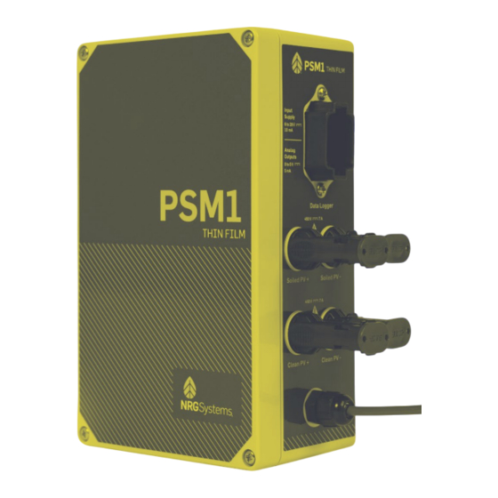
- Page 4 Sensors | Pulsed Soiling Module (PSM1) INTRODUCTION The Pulsed Soiling Module (PSM1) measures the Open Circuit Voltage and Short Circuit Current of a clean and soiled solar panel in accordance with IEC 61724-1. The equipment is intended to be used outdoors and is mounted on or near a solar panel array.
-
Page 5: Sensor/Product Identification
Sensors | Pulsed Soiling Module (PSM1) SENSOR/PRODUCT IDENTIFICATION PSM labels identify company, product, input and output values, and shock hazards. An example of the PSM1’s labeling is shown below. Details vary depending on the PSM1 kit. PSM1 Solar Kits: #19045 SRM Crystalline 30A PSM: Parts... -
Page 6: 19046 Srm Thin Film 4A Psm: Parts
NRG Instructions Sensors | Pulsed Soiling Module (PSM1) #19046 SRM Thin Film 4A PSM: Parts NRG Part Part Description Part Specification Number 18860 Pulsed Soiling PSM1, Thin Film Assembly Module 18888 Cable 30m cable 18890 DC Isolator 64 Amp (Disconnect) Sub-... -
Page 7: 18890 Subassembly: Dc Isolator Or "Solar Disconnect
NRG Instructions Sensors | Pulsed Soiling Module (PSM1) #18890 Subassembly: DC Isolator or “Solar Disconnect” NRG Part Part Description Part Specification Number 18623 Solar Disconnect 64 A, SRM 11044 Outdoor Label CLEAN 11046 Outdoor Label DIRTY 18718 Mount Solar Disconnect... -
Page 8: Safety Considerations / Warnings
NRG Instructions Sensors | Pulsed Soiling Module (PSM1) SAFETY CONSIDERATIONS / WARNINGS Warning symbols: This universal symbol represents a general warning and is marked on the unit and included in this manual. This universal symbol represents an electrical hazard and is marked on the unit and included in this manual. -
Page 9: Operating Environmental Conditions
NRG Instructions Sensors | Pulsed Soiling Module (PSM1) WARNING: Do not open the enclosure: There are no user-serviceable parts inside the product enclosure. Do not open it. Opening the enclosure may damage the product and/or interconnected equipment and risks bodily injury. -
Page 10: Installation
NRG Instructions Sensors | Pulsed Soiling Module (PSM1) INSTALLATION Considerations Location • Product is intended to be mounted to the pile, with the Solar Disconnect (if applicable) on the torque tube. • The standard 18634 MC4 cables that run from the PV modules to the Solar Disconnect to the PSM are 2 meters long. -
Page 11: Compatibility
NRG Instructions Sensors | Pulsed Soiling Module (PSM1) Compatibility • Data Logger Compatibility o NRG LOGR-S o NRG SymphoniePRO Logger o Any Data Logger which supports: 8-28 VDC, 20 mA Excitation Four 0 to 5 V Analog Inputs ... -
Page 12: Thin Film/Crystalline Psm1 Installation
NRG Instructions Sensors | Pulsed Soiling Module (PSM1) Thin Film/Crystalline PSM1 installation The following are step-by-step instructions for installing NRG Solar Kits 19045 and 19046. These both require a DC disconnect or “isolator” (see image below). The NRG kit number is #18890. The DC disconnect item number is #18623. - Page 13 NRG Instructions Sensors | Pulsed Soiling Module (PSM1) 1. Begin by loosely outlining where the various components will be installed and check cable lengths. 2. The #18890 – Solar Disconnect, should be mounted onto the torque tube near the two Soiling PV panels.
- Page 14 NRG Instructions Sensors | Pulsed Soiling Module (PSM1) 4. Mount the PSM onto the pile nearest to the DC Isolator, again using the provided hose clamps. The PSM may also be mounted to the Torque tube if there are cabling restrictions, be mindful of the suggested orientation.
- Page 15 The grounding cable should not be connected to the logger. WARNING: This is a safety critical step. Not connecting the PSM1 to earth ground may cause the PSM1 to be a shock hazard. WARNING: Ensure 18623 Solar Disconnect is turned to the OFF position 5.
- Page 16 WARNING Seal provides ingress protection against liquids. If liquid water or conductive contaminates gets inside the PSM1, it may cause arcing across terminals not designed to handle high voltages (e.g. sending 450 V to the attached logger to ground). NRG PSM1 Instructions support@nrgsystems.com | Page 16...
- Page 17 Ensure “Soiled” and “Clean” output from the disconnect are going to the corresponding PSM ports. 8. Turn the #18623 Solar Disconnect to ON. Complete assembly of PSM1 for Crystalline and Thin Film Configurations. NRG PSM1 Instructions support@nrgsystems.com | Page 17 Rev.
-
Page 18: Nrg 30 W Psm Installation
WARNING Seal provides ingress protection. If liquid water or conductive contaminates gets inside the PSM1, it may cause arcing across terminals not designed to handle high voltages (e.g. sending 450 V to the attached logger to ground). NRG PSM1 Instructions support@nrgsystems.com | Page 18... -
Page 19: Wiring And Configuration
NRG Instructions Sensors | Pulsed Soiling Module (PSM1) Wiring and Configuration Wiring LOGR-S: LOGR-S: Wiring Table - Analog Wire Color Function Termination Power Excitation Port - EXC Black Power Ground Port - GND Blue Soiled Isc Port - SIG+ Green... -
Page 20: Programming Logr-S
NRG Instructions Sensors | Pulsed Soiling Module (PSM1) Programming LOGR-S: Open a web browser and connect the logger using an Ethernet cable directly to the laptop or secure a wireless connection via static IP address while connected to the same local network as the logger. Enter the static IP address in the browser URL bar. -
Page 21: Logr-S Analog Channel Configuration Tables
NRG Instructions Sensors | Pulsed Soiling Module (PSM1) Navigate to Sensors > Analog channels to configure Isc and Voc Soiled and Clean and associated PVT1 channels. Use the table below to configure the channels based on PV module. LOGR-S Analog Channel Configuration Tables... - Page 22 NRG Instructions Sensors | Pulsed Soiling Module (PSM1) Navigate to Sensors > Soiling Ratio Setup Check box Compute under Compute Soiling Ratio and select the IEC 61724 Annex C radio button. NRG PSM1 Instructions support@nrgsystems.com | Page 22 Rev. 5.0...
- Page 23 NRG Instructions Sensors | Pulsed Soiling Module (PSM1) Standard Test Conditions for PV Modules should be 25.0 degrees C and 1000 W/m^2. The PV Panel specifications can be found on a label on the back of the PV panel and can vary from panel to panel.
- Page 24 NRG Instructions Sensors | Pulsed Soiling Module (PSM1) The specifications taken from this label are then input into the Clean and Soil PV Module forms below. Use the drop down menus to match the PSM and temperature sensors with their corresponding channels.
-
Page 25: Final Logr-S Checks
NRG Instructions Sensors | Pulsed Soiling Module (PSM1) Check sensor outputs to verify data. Daily Soiling Ratio data should start as close to 1.0 as possible when both modules are cleaned. Daily Soiling Ratio would follow the above format in your LOGR-S Sensor Outputs page. -
Page 26: Symphoniepro Logger Configuration
NRG Instructions Sensors | Pulsed Soiling Module (PSM1) SymphoniePRO logger Configuration: This PSM requires four channels to be fully functional. It can be installed on Analog 5V or 12V Excitation channels 16-19, or on Analog P-SCM channels 20-26. If installed on channels 20-26, it will need the #9132 P-SCM. -
Page 27: Programming Symphoniepro
NRG Instructions Sensors | Pulsed Soiling Module (PSM1) Programming SymphoniePRO: Open the SymphoniePRO Desktop App and connect the logger using a USB cable directly to the laptop or secure a connection via remote Metlink with the iPack static IP address. From the Fleet View, enter the logger and navigate to the Channels tab located on the left side of the window. -
Page 28: Symphoniepro Logger Configuration Table (Analog Channels 16-19 & P-Scm Channels 20-26)
NRG Instructions Sensors | Pulsed Soiling Module (PSM1) SymphoniePRO Logger Configuration Table (Analog Channels 16-19 & P-SCM Channels 20-26): 30 W PV Module 1st Channel 2nd Channel 3rd Channel 4th Channel Data Logging Mode Statistics Statistics Statistics Statistics Channel Type... -
Page 29: Final Symphoniepro Checks
NRG Instructions Sensors | Pulsed Soiling Module (PSM1) Final SymphoniePRO Checks: Pull-test all wires to ensure proper connection. If any of the wires come out of the wiring panel during pull-test: loosen the screw, insert the cable, and hand-tighten with a mini flathead screwdriver. -
Page 30: Data Processing - Soiling Calculation
PV farm’s energy production can be characterized. If using the PSM1 with a SymphoniePRO, the calculation of the soiling ratio must be done in −... -
Page 31: Normalization Process
NORMALIZATION PROCESS The Normalization Process is performed post-panel cleaning and resets the offset calculation for soiling measurement utilizing the NRG Pulsed Soiling Module (PSM1) paired with NRG LOGR or SymphoniePRO data loggers. This process is the same for both the Crystalline (c-Si) and ThinFilm PSM1 versions. -
Page 32: Offset Calculation Procedure
NRG Instructions Sensors | Pulsed Soiling Module (PSM1) Offset Calculation Procedure Turn the PV Array DC Isolator switch OFF, so that the soiling modules are held in open circuit. Clean both PSM-connected PV modules (Dirty and Clean). a. Clean with deionized water and a soft, non-abrasive cloth. Be mindful of debris on the panels when cleaning so as not to damage the modules. - Page 33 NRG Instructions Sensors | Pulsed Soiling Module (PSM1) b. SymphoniePRO data logger: Channels tab> Analog 5V or 12V Excitation/Analog (P-SCM) Channels> PSM (c-Si or ThinFilm) Isc Soil Channel and PSM (c-Si or ThinFilm) Isc Clean Channel. Turn the PV Array DC Isolator switch ON, so that the soiling modules are actively connected to the PSM1.
- Page 34 NRG Instructions Sensors | Pulsed Soiling Module (PSM1) Collect data measurements on a day with a stable irradiance pattern, without clouds, for one hour before and one hour after solar noon (two hours total). Extract the short circuit current data of the two modules (PSM (c-Si or ThinFilm) Isc Clean and PSM (c-Si or ThinFilm) Isc Soil) when the irradiance was greater than 500 W/m2.
- Page 35 NRG Instructions Sensors | Pulsed Soiling Module (PSM1) After configuring the PSM (c-Si or ThinFilm) Isc Soiled Channel with the calculated Offset, the short-circuit currents of the two modules should be equalized. a. LOGR data logger final check: View live data on the Sensor Outputs page of the web UI.
-
Page 36: Maintenance And Service
NRG Instructions Sensors | Pulsed Soiling Module (PSM1) MAINTENANCE AND SERVICE PSM1 Maintenance The PSM1 should not require physical maintenance and there are no serviceable parts in the 18872/18860 PSM1. Should an issue occur, contact NRG Technical Services at support@nrgsystems.com. WARNING Should any part of the system need to be returned or replaced, ensure the 18623 Solar Disconnect is turned to OFF prior to any additional work. - Page 37 NRG Instructions Sensors | Pulsed Soiling Module (PSM1) Clean/Soiled VOC 0.145 to 0.244 0.145 to 0.638 0.982 to 4.440 Clean/Soiled ISC 0.083 to 0.494 1.647 to 4.953 0.165 to 0.659 Accuracy Specifications (k=2) at Recommended Conditions Clean/Soiled VOC 101.5805887 101.4066317 101.2142007...
- Page 38 Ratings. Contact NRG Systems for more information and/or assistance. 3: Fluctuations (noise / ripple) on the power supply may reduce system accuracy 4: Product may be operated at higher altitudes with reduced ratings. Contact NRG Systems for more information. Product is designed for outdoor use and in wet locations.
-
Page 39: Contact Information
NRG Instructions Sensors | Pulsed Soiling Module (PSM1) CONTACT INFORMATION To return a defective product, request an RMA (return merchandise authorization) number by calling us at the number below or by emailing support@nrgsystems.com, or by submitting a request through our website’s Technical Support area.
Need help?
Do you have a question about the PSM1 and is the answer not in the manual?
Questions and answers