
Summary of Contents for PSS ROADQUAKE RAPTOR ROVER
- Page 1 OPERATORS MANUAL SCAN FOR A DIGITAL COPY OF THIS MANUAL. CONTACT: Call 800.662.6338 to talk to a Customer Service Representative. HOURS: 8 AM to 5 PM (E.T.) Monday through Friday...
-
Page 2: Table Of Contents
TABLE OF CONTENTS PAGE SECTION #1 PAGE SECTION #11 ROVER RAPTOR AND ™ INTRODUCTION HOST VEHICLE PAGE SECTION #2 PAGE SECTION #12 ROVER PART FEATURES IDENTIFICATION OF RAPTOR PAGE SECTION #3 PAGE SECTION #13 ROVER PRIOR TO USE IN MAINTENANCE A WORK ZONE PAGE SECTION #4... -
Page 3: Rover Introduction
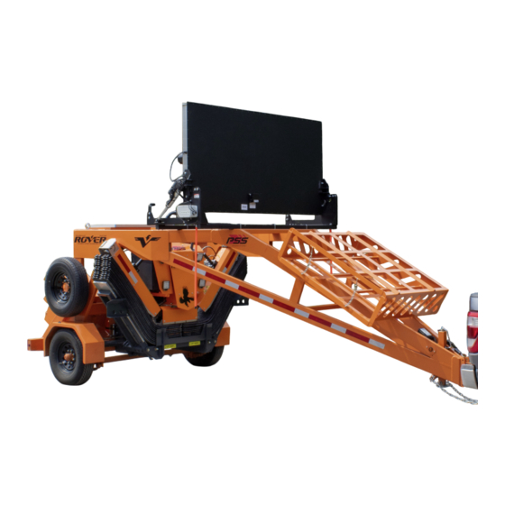
™ Strips (TPRS). By keeping workers out of live traffic, the use of RoadQuake2F TPRS was easier and safer than ever before. To make RAPTOR more accessible, pss designed the dedicated transport RAPTOR trailer, the Rover ™ RAPTOR Rover is designed specifically for the transport of RAPTOR and mounts to the back of the operating vehicle rather than the front. -
Page 4: Rover Part Identification
Trailer Jack Sign Stand Holder Sign Storage Axle Arrow Board (if equipped)* Battery Box *Arrow board and controls may be different depending if the arrow board was purchased through PSS or alternative sources. SIDE VIEW. BACK VIEW. RAPTOR ™ Rover ™... -
Page 5: Rover Maintenance
Arrow boards are an optional feature on Rover that can be NOTICE NOTICE purchased with Rover through PSS or user installed. All RAPTOR wireless remote frequencies arrow boards purchased through PSS are manufactured can interfere with the wireless arrow board by Vermac. -
Page 6: Rover Power Information
04 ROVER POWER INFORMATION 4.2 – VICTRONCONNECT APP 4.1 – ROVER POWER SUPPLY There is an app called VictronConnect which allows you to monitor power usage and charging. You may have to open the battery box for Bluetooth to sucessfully connect. The Rover's batteries are charged from either the supplied 100-watt solar panel or direct from the tow vehicle's charging system. -
Page 7: Rover Towing Information
05 ROVER TOWING INFORMATION 5.1 – ROVER LOADING AND BALANCE 5.4 – ROVER HITCH IDENTIFICATION The Rover is designed exclusively to haul the RAPTOR Rumble Strip Handling Machine with 12 RoadQuake2F Rumble Strips and 12 signs and Sign Stands. Do not use these compartments for storage of any other materials. - Page 8 05 ROVER TOWING INFORMATION 5.5 – HITCHING ROVER TO VEHICLE (CON'T) Verify that the Rover is riding level with the host vehicle. Connect the Emergency Brake Tether (I) to secured If Rover is not riding level, raise or lower the Rover attachement point on the towing vehicle.
-
Page 9: Raptor Mounting On Rover
6.2 – POST-PURCHASE RAPTOR MODIFICATIONS Rover is reverse compatible with wall RAPTOR models. Customers should consult with PSS to confirm if the remote of the RAPTOR being mounted needs to be updated to function with Rover. Please call PSS as 800-662-6338. - Page 10 RAPTOR MOUNTING ON ROVER 6.3 – MOUNTING RAPTOR ONTO EMPTY ROVER RAPTOR Lower the trailer frame to the ground. Being careful not to hit the RAPTOR. ROVER Adjust the RAPTORs Mounting Hooks to the farthest inboard position in the mounting slots. This will allow the RAPTOR to “center”...
-
Page 11: Rover Appendix
THE INFORMATION CONTAINED IN THIS Rover Electrical - A FINISH DRAWING IS THE SOLE PROPERTY OF see notes PSS, INC. ANY REPRODUCTION IN PART OR AS A WHOLE WITHOUT THE WRITTEN SCALE: 1:4 WEIGHT: SHEET 1 OF 1 PERMISSION OF PSS, INC IS PROHIBITED. -
Page 12: Raptor Safety Instructions
RAPTOR SAFETY INSTRUCTIONS WARNING WARNING WARNING DANGER DANGER DANGER 8.1 – SAFETY INSTRUCTIONS & HAZARD WARNINGS CRUSHING CRUSHING CRUSHING CUTTING HAZARD CUTTING HAZARD CUTTING HAZARD DANGER DANGER DANGER Severe injury or death may result if instructions are not followed. DANGER DANGER DANGER ARNING... -
Page 13: Warranty
8.7 – WARRANTY disk drives, payment cards, data storage devices, watches, hearing aids, and speakers. RAPTOR RSHMs sold by PSS are warranted by PSS to be free from defects in material and workmanship for one (1) years 8.3.3 – NOISE LEVEL from the date of shipment. -
Page 14: Raptor Introduction
RAPTOR INTRODUCTION 9.1 – INTRODUCTION Welcome to the PSS instruction manual for RoadQuake ™ RAPTOR Rumble Strip Handling Machine. ™ In this manual, we will discuss RAPTOR’s basic features and functions, how it works, and how to troubleshoot and maintain the device. -
Page 15: Raptor Overview
RAPTOR OVERVIEW 10.1 – RAPTOR KEY COMPONENTS NUM PIECE NAME DESCRIPTION IMAGE Alignment Rod Component on each wing allows for the realignment of RQ TPRS. Guide Markers Component on each wing showing the user the width of RAPTOR TPRS Tray Housing location of RQ TPRS within RAPTOR. - Page 16 RAPTOR OVERVIEW 10.2 – RAPTOR IN TRANSPORT MODE (WINGS UP) Use this mode to transport RAPTOR to and from job sites. Alignment Rod Work Lights Guide Markers Forklift Support TPRS Tray Indicator Lights Magnet Bar Forward-Facing Camera Auxiliary Headlights Downwad-Facing Camera (inside of the arm) ™...
- Page 17 Measurement Device Equipment (DME not 10.5 – DIN PLATE, FRONT VIEW provided by PSS) DIN Plate is to be made of 1/2 - 5/8" (1.3 - 1.6 cm) Hot Rolled Steel (HRS). Securely Mount to frame of host vehicle. CAD data available upon request.
-
Page 18: Raptor And Host Vehicle
Inspect RAPTOR upon arrival. Contact PSS immediately of RAPTOR's frame. The adjustable mounting hooks if you discover any damage: PSS Technical Support at contain multiple-laminated plates to accommodate 800-662-6338. various thicknesses of DIN plates. - Page 19 #2 gauge wires to accommodate the 140 peak Amps required to run the machine. Use the proper-size electrical cable to minimize voltage drop. PSS recommends a power- 11.3.2 – APPROPRIATE MOUNTING HEIGHT pole type connector. (Not included with RAPTOR.) When...
-
Page 20: Features Of Raptor
The downward-facing camera broadcast, used to retrieve and align RQ TPRS. 12.3 – DISTANCE MEASURING EQUIPMENT ( DME ) To measure distances between strips while deploying them, PSS recommends that operators install an (optional) Distance Measuring Equipment (DME) device in the RAPTOR vehicle. RAPTOR ™... - Page 21 FEATURES OF RAPTOR 12.5 – USE OF REMOTE 12.4 – FUNCTIONS OF REMOTE CONTROL RAPTOR operates with a wireless remote control transmitter To turn the remote on, release the red E-Stop button, » that features eight multi-functional buttons. The battery status turn clockwise ¼...
-
Page 22: Prior To Use Ina Work Zone
13.2 – DETERMINING YOUR TRAFFIC CONTROL PLAN Review the specific traffic control plan for use of RQ TPRS in work zones. If no TTC plan exists, use the PSS "RoadQuake: Best Practices for Optimal Use" guide book to determine distances between strips. -
Page 23: Operating Raptor
14 OPERATING RAPTOR 14.1 – POWER RAPTOR ON To start RAPTOR, the operator must leave the cab, or, from the cab, direct a co-worker outside the vehicle to perform the following steps: » On the driver side of the vehicle, locate the rotary switch on the electrical cabinet. -
Page 24: Operating Raptor - Deployment
OPERATING RAPTOR - DEPLOYMENT 15.1 – DEPLOYING RQ TPRS An individual RoadQuake Rumble Strip measures 11 ft (31 If your RAPTOR is not centered in the deployment cm) long, and covers an entire lane of traffic. Before deploying area, press and hold buttons 3 ( ← ) or 4 ( → ) to laterally a strip, position the vehicle so that it is centered in the lane. -
Page 25: Operating Raptor - Retrieval
16.1 – BEFORE RETRIEVING RQ TPRS Press and hold button 2 ( ↑ ) to raise the arm up and out PSS recommends the removal of all RQ TPRS from the of the tray. The green indicator light will begin flashing. - Page 26 16.3 – REALIGNING RQ TPRS RQ TPRS may skew during use in an active work zone. See PSS Best Practices Guide for acceptable movement. Operators can realign skewed strips during the day. If required, follow the steps in Section 15.2 up to step 4. Once the TPRS is realigned, press and hold button 1 ( ↓...
-
Page 27: Raptor Troubleshooting
RAPTOR TROUBLESHOOTING 17.1 – MANUALLY RESTORE RAPTOR TO 17.2 – ELECTRICAL TROUBLESHOOTING MODE WARNING WARNING WARNING DANGER DANGER DANGER TRANSPORT MODE RAPTOR features a Troubleshooting Mode, which allows CRUSHING CRUSHING CRUSHING operators to test every hydraulic function. ARNING ARNING CUTTING HAZARD CUTTING HAZARD CUTTING HAZARD During restoration, once valve operator... -
Page 28: Raptor Overall Maintenance
» » Check alignment rods – Inspect to ensure the rods engage the road surface. Replace as required. PSS recommends operators carry a spare set in the RAPTOR vehicle. » Inspect electrical cabinet for accumulated moisture To remove the Mast: Monthly: »... -
Page 29: Maintenance Log
MAINTENANCE LOG 19.1 – MAINTENACE LOG _______________________________________________________________________________________________ _______________________________________________________________________________________________ _______________________________________________________________________________________________ _______________________________________________________________________________________________ _______________________________________________________________________________________________ _______________________________________________________________________________________________ _______________________________________________________________________________________________ _______________________________________________________________________________________________ _______________________________________________________________________________________________ _______________________________________________________________________________________________ _______________________________________________________________________________________________ _______________________________________________________________________________________________ _______________________________________________________________________________________________ _______________________________________________________________________________________________ _______________________________________________________________________________________________ _______________________________________________________________________________________________ _______________________________________________________________________________________________ _______________________________________________________________________________________________ _______________________________________________________________________________________________ _______________________________________________________________________________________________ _______________________________________________________________________________________________ _______________________________________________________________________________________________ _______________________________________________________________________________________________ _______________________________________________________________________________________________ _______________________________________________________________________________________________ ______________________________________________________________________________________________ _______________________________________________________________________________________________ ______________________________________________________________________________________________ _______________________________________________________________________________________________ _______________________________________________________________________________________________ _______________________________________________________________________________________________ _______________________________________________________________________________________________ _______________________________________________________________________________________________ _______________________________________________________________________________________________ _______________________________________________________________________________________________ _______________________________________________________________________________________________ _______________________________________________________________________________________________... - Page 30 MAINTENANCE LOG 19.1 – MAINTENACE LOG _______________________________________________________________________________________________ _______________________________________________________________________________________________ _______________________________________________________________________________________________ _______________________________________________________________________________________________ _______________________________________________________________________________________________ _______________________________________________________________________________________________ _______________________________________________________________________________________________ _______________________________________________________________________________________________ _______________________________________________________________________________________________ _______________________________________________________________________________________________ _______________________________________________________________________________________________ _______________________________________________________________________________________________ _______________________________________________________________________________________________ _______________________________________________________________________________________________ _______________________________________________________________________________________________ _______________________________________________________________________________________________ _______________________________________________________________________________________________ _______________________________________________________________________________________________ _______________________________________________________________________________________________ _______________________________________________________________________________________________ _______________________________________________________________________________________________ _______________________________________________________________________________________________ _______________________________________________________________________________________________ _______________________________________________________________________________________________ _______________________________________________________________________________________________ ______________________________________________________________________________________________ _______________________________________________________________________________________________ ______________________________________________________________________________________________ _______________________________________________________________________________________________ _______________________________________________________________________________________________ _______________________________________________________________________________________________ _______________________________________________________________________________________________ _______________________________________________________________________________________________ _______________________________________________________________________________________________ _______________________________________________________________________________________________ _______________________________________________________________________________________________ _______________________________________________________________________________________________...
- Page 31 MAINTENANCE LOG 19.1 – MAINTENACE LOG _______________________________________________________________________________________________ _______________________________________________________________________________________________ _______________________________________________________________________________________________ _______________________________________________________________________________________________ _______________________________________________________________________________________________ _______________________________________________________________________________________________ _______________________________________________________________________________________________ _______________________________________________________________________________________________ _______________________________________________________________________________________________ _______________________________________________________________________________________________ _______________________________________________________________________________________________ _______________________________________________________________________________________________ _______________________________________________________________________________________________ _______________________________________________________________________________________________ _______________________________________________________________________________________________ _______________________________________________________________________________________________ _______________________________________________________________________________________________ _______________________________________________________________________________________________ _______________________________________________________________________________________________ _______________________________________________________________________________________________ _______________________________________________________________________________________________ _______________________________________________________________________________________________ _______________________________________________________________________________________________ _______________________________________________________________________________________________ _______________________________________________________________________________________________ ______________________________________________________________________________________________ _______________________________________________________________________________________________ ______________________________________________________________________________________________ _______________________________________________________________________________________________ _______________________________________________________________________________________________ _______________________________________________________________________________________________ _______________________________________________________________________________________________ _______________________________________________________________________________________________ _______________________________________________________________________________________________ _______________________________________________________________________________________________ _______________________________________________________________________________________________ _______________________________________________________________________________________________...
- Page 32 Call 800.662.6338 to talk to a Customer Service Representative. HOURS: Follow us on: 8 AM to 5 PM (E.T.) Monday through Friday We are a proud member of: 2444 Baldwin Road, Cleveland, OH 44104 800.662.6338 PSS-Innovations.com Copyright © 2024 10/24...
Need help?
Do you have a question about the ROADQUAKE RAPTOR ROVER and is the answer not in the manual?
Questions and answers