Advertisement
Quick Links
MCC3723-F Installation Guide
AU3TECH RESEARCH PTY LTD
Email: info@au3tech.com
Web: www.au3laser.com
1. Product Overview
The MCC3723-F motion control card is a new generation numerical control system
specially developed for the field of fiber laser cutting, with abundant peripheral
resources and powerful functions.
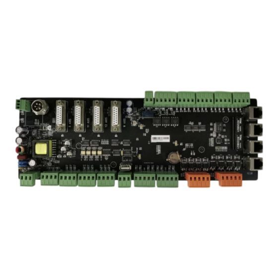
2. Schematic diagram of CNC board
Description of each port
Port name
Power input +24V
Axis limit
input
1
Wuhan Au3tech Intelligent Technologies Co., Ltd.
Effect
DC24V input positive
PG
Protective grounding
0V
DC input negative, power ground.
X+
X-axis positive limit input,
dedicated signal, active low
X0
X-axis origin signal, dedicated
signal, active low
X-
X-axis negative limit input,
Remarks
It is recommended to
use 24V/10A DC power
supply
X-axis limit input
Advertisement

Summary of Contents for Au3Tech MCC3723-F
- Page 1 Email: info@au3tech.com Web: www.au3laser.com 1. Product Overview The MCC3723-F motion control card is a new generation numerical control system specially developed for the field of fiber laser cutting, with abundant peripheral resources and powerful functions. 2. Schematic diagram of CNC board...
- Page 2 Wuhan Au3tech Intelligent Technologies Co., Ltd. dedicated signal, active low Ground, the common terminal of X- axis limit signal. Y-axis positive limit input, Y-axis limit input dedicated signal, active low Y-axis origin signal, dedicated signal, active low Y-axis negative limit input,...
- Page 3 Wuhan Au3tech Intelligent Technologies Co., Ltd. DO11 3rd general output port DO12 The 4th general output port DO13 The 5th thyristor output port DC 24V output, drive current 1A. DO14 No. 6 thyristor output port Thyristor output common port DO15 No.
- Page 4 Wuhan Au3tech Intelligent Technologies Co., Ltd. the default low level is active DI14 The 14th general-purpose input port, the default low level is active DI15 The 15th general-purpose input port, the default low level is active Input signal common Ethercat...
- Page 5 MCC3723-F CNC board supports 35mm rail installation, length (315mm) X width (120mm) 3.3 Installation limit/other IO ports Limit input: The MCC3723-F numerical control board card provides four-axis limit input of X-axis, Y- axis, Z-axis and W-axis. Take the X axis as an example to install the axis limit signal.
- Page 6 The output method is shown in the figure below: The MCC3723-F CNC board provides 4 servo control interfaces, which are X axis, Y1 axis, Y2 axis, and W axis. The interface form is DB15 Female seat. When the system is configured in dual-drive mode, the Y1 axis and Y2 axis respectively control the two servo drives of the Y axis.
- Page 7 Wuhan Au3tech Intelligent Technologies Co., Ltd. The MCC3723-F numerical control board adopts "pulse + direction signal" to control the servo drive, which can support various servo drives such as Yaskawa, Panasonic, Fuji, Delta, Inovance, etc. Panasonic A5/A6The series of low-speed pulse wiring diagrams are as follows:...
- Page 8 Wuhan Au3tech Intelligent Technologies Co., Ltd. Yaskawa ∑—V7The series wiring diagram is as follows: The basic parameter settings of Yaskawa ∑—ⅴ7 series are as follows: Parameter Set value Meaning Pn000 001X Set the servo control mode to position mode Pn00B...
- Page 9 Wuhan Au3tech Intelligent Technologies Co., Ltd. The wiring diagram of Fuji A5 series is as follows: Fuji A5 series basic parameter settings Parameter Set value Meaning PA-101 Set the servo control mode to position mode PA-103 Set "pulse + direction" mode...
- Page 10 Wuhan Au3tech Intelligent Technologies Co., Ltd. SchneiderLexium-23/26DSeries wiring diagram SchneiderLexium-23/26DSeries basic parameter setting Parameter Set value Meaning name P1-00 0102 Set pulse method P1-01 0000 Location mode P2-00 Factory Position control proportional gain, real-time value 35 adjustment according to the actual situation...
- Page 11 Wuhan Au3tech Intelligent Technologies Co., Ltd. P2-15 0000 Invalidate DI6 function plan P2-16 0000 Invalidate DI7 function plan P2-17 0000 Invalidate DI8 function plan P2-22 0007 Make DO5 function plan as servo alarm P2-68 0001 When L1/L2 and SON are enabled at the same time,...
- Page 12 Wuhan Au3tech Intelligent Technologies Co., Ltd. P2-10 Make DI1 function planning as servo enable, logic as normally open P2-14 Make DI5 function planning as alarm clear, logic as normally open P2-15 Invalidate DI6 function plan P2-16 Invalidate DI7 function plan...
- Page 13 Wuhan Au3tech Intelligent Technologies Co., Ltd. Parameter Set value Meaning name H02-00 1—Location mode Mode selection H02-02 0—Forward mode Rotation direction selection Output pulse feedback direction H02-03 0—Forward mode selection H03-08 2—Fault reset DI4 terminal function selection H03-10 1—Servo enable DI5 terminal function selection 1—Output...
- Page 14 Wuhan Au3tech Intelligent Technologies Co., Ltd. Lei Sai L5/L7Series basic parameter setting Parameter Set value Meaning name PR001 0000 Location mode Factory Servo rigidity is adjusted in real time according PR003 value 13 to the actual situation, generally not less than...
- Page 15 Wuhan Au3tech Intelligent Technologies Co., Ltd. Fuji A5-SMART-PLUS series wiring diagram Fuji A5-SMART-PLU series parameters Parameter name Reference Meaning value P1-01 Location mode P1-03 Command pulse/command symbol P1-05 10000 Every rotation1 Number of command input pulses per week P1-08 2500...
- Page 16 Wuhan Au3tech Intelligent Technologies Co., Ltd. P1-14 Initial Load moment of inertia ratio value 1.0 P1-15 Initial Self-tuning gain1 value 12 P1-16 Initial Self-tuning gain2 value 4 Hechuan X3Wiring diagram Hechuan X3Parameter description Parameter Set value Meaning name P00-00 Motor rotation direction...
- Page 17 Wuhan Au3tech Intelligent Technologies Co., Ltd. P00-07 Pulse + direction (0 positive logic, 1 negative logic) P00-08 10000 Number of command pulses per motor revolution (32 bits) P00-10 Default value Numerator of electronic gear ratio (32 bits) (1-- 1073741824) P00-12...
- Page 18 Wuhan Au3tech Intelligent Technologies Co., Ltd. 3.6 Connect the laser The MCC3723-F numerical control board can be connected to the laser through the serial port/network port, and it can also be connected to the laser through the I/O port signal.
- Page 19 Wuhan Au3tech Intelligent Technologies Co., Ltd. Note: The wiring methods of other lasers (such as Lianpin, Fibo, Kaplan, Chuangxin, Guozhi, etc.) can be referred to, but not limited to this wiring method. IPG-YLR laser and digital control board IO port docking diagram:...
- Page 20 5V switching power supply to the COM port of the CNC board. No 5V output is provided. 3.7 Connect to a computer The MCC3723-F CNC board can be directly connected to the computer (industrial computer) through any network port, which is convenient and quick. 3.8 Install the power supply When all the other peripherals are connected, 24V power supply is needed for the CNC board.
- Page 21 Wuhan Au3tech Intelligent Technologies Co., Ltd. Because the WINDOWS system used by some customers does not open the function of automatically setting the local IP, The user can also manually set the computer host IP address: 10.1.1.10, subnet mask: 255.255.255.0, default gateway: 10.1.1.1 Description:The IP addresses of the height controller and the numerical control system have been set by default at the factory, and the user does not need to change them.
- Page 22 Wuhan Au3tech Intelligent Technologies Co., Ltd. 4.3.1 Motion axis configuration The motion axis mainly configures axis parameters and return to original parameters, as shown in the figure below: Refer to the table below for parameters and meanings: Motion axis Parameter name...
- Page 23 Wuhan Au3tech Intelligent Technologies Co., Ltd. logic logic open axis should be consistent. Encoder reverse Encoder feedback signal Uncheck After checking, the reverse direction of the encoder data collected by the system should be selected according to the actual situation...
- Page 24 Wuhan Au3tech Intelligent Technologies Co., Ltd. multiplication change Back to Use Z-phase Select motor for origin Uncheck origin signal signalZPhase signal Sampled signal Origin signal selection, Origin If the user wants to use the including origin/Limit axis limit signal as the...
- Page 25 Wuhan Au3tech Intelligent Technologies Co., Ltd. 2. Configure machine tool limit/origin signal and machine format The system can support photoelectric/mechanical travel switches, and the normally open/normally closed logic can be set. The user must correctly set the limit of each axis, otherwise the limit signal cannot be activated correctly.
- Page 26 Wuhan Au3tech Intelligent Technologies Co., Ltd. The user can set the corresponding return parameters according to the above figure. It is recommended not to set the return speed too fast to ensure the smooth and safe return process. 4.3.2 Laser configuration and debugging...
- Page 27 Whether the light and the laser are normal. 4.3.4 Electric focusing head configuration When MCC3723-F matches the Osendico electric focusing head, select the onboard serial port option. F rom the syst em a naly sis —E lect ric focu s en ter the four th a xis e lect ric f ocus par amet er i nter face , an d co nfig ure the rele vant par amet er s of the c utti ng h ead corr ectl y.
- Page 28 Wuhan Au3tech Intelligent Technologies Co., Ltd. 4.3.5 Gas configuration and debugging The system supports two gas control methods: high and low pressure valve/proportional valve. Corresponding gas ports can be configured according to needs.
- Page 29 Wuhan Au3tech Intelligent Technologies Co., Ltd. Description: The air pressure correction only supports the gas configured as a proportional valve. By setting the number of air pressure correction points, the voltage of each point and the corresponding air pressure value, the precise control of the air pressure is ensured.
-
Page 30: Trial Run
Wuhan Au3tech Intelligent Technologies Co., Ltd. 5. Trial run After the components are configured, the trial operation can be started. The user can confirm according to the following steps: 1. Confirm whether the running direction of each axis is correct. - Page 31 Wuhan Au3tech Intelligent Technologies Co., Ltd. When the system works for the first time, be sure to calibrate the float. Please ensure the following content in order for calibration: ⚫ Just below the cutting headPlacedSheet metal to be calibrated ⚫...
- Page 32 Wuhan Au3tech Intelligent Technologies Co., Ltd. Note: The origin fine adjustment function is used to correct the zero position of the electric focusing window. Generally, no user adjustment is required. 5. Confirm whether the laser/gas is working properly. Step 1: Set the gas type, gas delay, laser burst power, frequency and other parameters in the operating parameters.
Need help?
Do you have a question about the MCC3723-F and is the answer not in the manual?
Questions and answers