Advertisement
Available languages
Available languages
Quick Links
Voyager® ID Brake Control (90930)
Trailer Brake Control
For 2, 4 and 6 brake applications
Scan QR code for French or
Spanish language instructions
and Enter Part number 90930.
READ THIS FIRST:
Important Safety Information:
WARNING
— To prevent Serious INJURY, DEATH or PROPERTY DAMAGE.
•
Always read and follow all instructions carefully before installing or operating
the Voyager ID Brake Control. Wear safety glasses and use all safety precautions
during installation.
•
Keep these instructions with the brake control for future reference.
•
CHECK periodically that your Brake Control Unit, LED indicator and Manual Knob
Control Unit are securely mounted to your vehicle.
•
INSPECT and ADJUST your trailer brakes every 3000 miles or as use and perfor-
mance requires.
•
BEFORE use, ALWAYS read, understand and follow all warnings and instructions
for your vehicle and for your trailer.
•
NEVER exceed the lowest rated capacity of either your vehicle, hitch or trailer.
Consult the owner's manual for your vehicle and your trailer.
•
TEST your BRAKE CONTROL UNIT settings each time a trailer is attached to your
vehicle.
•
ALWAYS wear your seatbelt.
•
SLOW DOWN when towing, NEVER exceed the posted speed limit.
Website: www.horizonglobal.com | Technical Assistance: 800-632-3290 | TechnicalSupport@horizonglobal.com
©2024 Horizon Global Corporation
90930INP
MOUNTING LOCATION:
NOTE: The Brake Control Unit & Manual Knob Control Unit are designed to be
mounted on or around the vehicle dash panel. Consider the location of both units
relative to each other and verify harness routing before drilling any holes.
WARNING— Correct orientation and mounting of the Brake Control Unit is
required for proper operation. The units must be securely mounted to a solid
surface.
WARNING—To prevent SERIOUS INJURY, DEATH or DAMAGE to the vehicle,
make sure the area behind the dash panel is clear before drilling or mounting the
bracket with screw.
1. Select a suitable mounting location for the Brake Control Unit & Manual Knob
Control Unit. (See Mounting Orientation Considerations)
2. Remove the panel and use the Drill hole Guide to mark the surface for the cen-
ters of the control and LED holes.
NOTE: Measure Drill hole Guide to ensure the box is scaled 1" x 1" before drilling.
NOTE: Test fit units to ensure any removed panels can be reinstalled after installa-
tion of the units before drilling any holes.
3. Drill the top hole for the LED using a 7/64" drill bit.
4. Drill the bottom hole for the Manual Knob Control Unit using a 13/32" drill bit.
5. Install the Manual Knob Control Unit LED and shaft post from the rear side thru
the dash panel holes.
6. Install the nut and tighten securely. Do
not overtighten
7. Rotate the shaft clockwise unit it stops
and install the knob on the shaft aligning
largest LED indicator position.
8. Using bracket or double sided tape pro-
vided, secure the Brake Control Unit (See
Mounting Orientation Considerations)
NOTE: The Brake Control Unit must be se-
curely mounted to a solid surface.
Do not tie wrap.
THIS PACKAGE INCLUDES:
(1) Brake Control Unit
(1) Instructions for installation and Operations
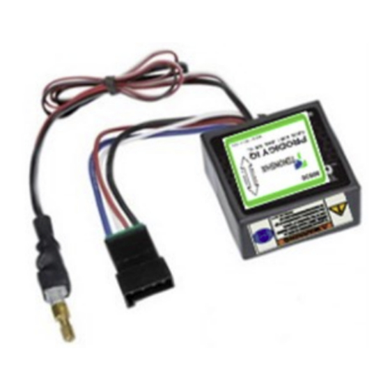
COMPONENTS OF THE BRAKE CONTROL UNIT:
A) Brake Control Unit
B) Tekonsha Universal Brake Control Plug & Play
Harness
C) Manual Knob Control Unit
D) Knob Assembly
E) Mounting hardware Kit
F) Scissors
G) Drill Hole Guide
H) Nut
I) Foam pad
J) Universal wire Harness
D
E
H
02-28-24
Rev. A
MOUNTING ORIENTATION CONSIDERATIONS:
WARNING— For proper operation, the Brake Control Unit MUST be mounted
with the arrow on the label in the direction of travel. See Figure B
1. Front of the Brake Control Unit must be horizontal
(+/- 20 degrees). See Figure B
2. The Brake Control Unit MUST be parallel to Direc-
tion of travel (+/- 20 degrees). See Figure B
NOTE: The Voyager ID can be mounted
out of sight under the dash. It can be
mounted at any rotation angle (0 to 360
degrees); as long as the arrow on the label
must point in the direction of travel. See
Figure C
The Voyager ID as viewed from the side. See Figure C
3. Determine mounting location based on direction of
travel.
4. Select bracket or foam pad for installation.
Option 1—Bracket
•
Slide bracket until locking tab is en-
gaged with the bracket. Using supplied
screw, attach unit to desired location.
Option 2—Foam Pad
•
Remove tape from one side, firmly
attach to unit.
•
Remove tape from other side and
WARNING— DRILLING
•
Verify what is behind any surface prior to drilling to avoid damage to the
vehicle and/or personal injury. Do not drill into any exposed surfaces.
NOTE: TAPE
•
Clean mounting location using a 50-50 mixture of rubbing alcohol and water.
•
Knob control should be mounted in an accessible location to the driver at all
times.
REQUIRED TOOLS AND MATERIAL (NOT INCLUDED):
WARNING— If you need additional assistance or do not have the tools
F
required, stop the installation and contact a professional installer.
TOOLS REQUIRED (NOT INCLUDED)
A) Drill
B) Drill Bits: 7/64"(LED), 13/32"(POT)
C) Center Punch
D) Safety Glasses
G
E) Wire Cutters
F) Crimp Tool
Note: Measure to ensure the box is
scaled 1" x 1" before cutting.
G) Voltage Tester
A
H) Panel removal tools
C
B
MATERIAL REQUIRED (NOT INCLUDED—See Wiring options 1 or 2)
I
Wiring legend:
Automatic reset circuit breaker (20 amp for 1-2 axles, 30 amp for 3 axles)
J
Assorted ring terminals and Butt Connectors.
WIRING OPTIONS:
The Voyager ID comes equipped with a Plug & Play Connector exiting at the
back of the control.
OPTION 1—Plug & Play
If your vehicle is equipped with a factory tow package, brake control function
wires with a connector may exist under the vehicle dash. Consult the vehicle
manual or call for the location of the harness. A vehicle-specific plug-and-play
harness may be purchased separately. For easy installation, simply plug the
vehicle specific connector into the factory tow package harness and plug the
other end directly into the Connector Plug & Play Connector on the brake
control. Continue to Controls & Indicators.
OPTION 2 —Universal Installation
Important Facts to Remember:
Figure B
WARNING— Reversing BLACK and WHITE wires or improper wiring will
damage or destroy brake control.
WARNING— Be sure to solidly connect all four wires or brake control will
not function properly.
WARNING— Use of proper gauge wire when installing the brake control is
CRITICAL: Smaller gauge wire may result in less than efficient braking.
D
E
F
G
BLACK Wire (Positive Battery)
WHITE Wire (Negative Battery)
RED Wire (Cold side of the stoplight switch)
BLUE Wire (Brake output to trailer)
A
B
C
H
Advertisement

Subscribe to Our Youtube Channel
Related Manuals for Voyager ID 90930


Summary of Contents for Voyager ID 90930
- Page 1 NOTE: The Brake Control Unit & Manual Knob Control Unit are designed to be WARNING— For proper operation, the Brake Control Unit MUST be mounted The Voyager ID comes equipped with a Plug & Play Connector exiting at the mounted on or around the vehicle dash panel. Consider the location of both units with the arrow on the label in the direction of travel.
-
Page 2: Operation Controls And Indicators
WIRE INSTALLATION INSTRUCTIONS: SET UP: MANUAL OVERRIDE BUTTON: 1. The brake control must be installed with a 12 volt negative ground system. WARNING— Test your Brake Control Unit settings before each use: The Manual Override button is located on • 2. -
Page 3: Emplacement De Montage
AVERTISSEMENT — Pour un fonctionnement correct, l'unité de commande de Le Voyager ID est équipé d'un connecteur Plug & Play qui sort à l'arrière de la manuels sont conçues pour être montées sur ou autour du tableau de bord du frein DOIT être montée avec la flèche de l'étiquette dans le sens de la marche. - Page 4 INSTRUCTIONS D'INSTALLATION DU FIL: INSTALLER: BOUTON DE COMMANDE MANUELLE: 1. La commande de frein doit être installée avec un système de mise à la terre AVERTISSEMENT — Testez les réglages de votre unité de contrôle des freins Le bouton de neutralisation manuelle est négative de 12 volts.
- Page 5 NOTA: La Unidad de Control de Freno y la Unidad de Control de Perilla Manual ADVERTENCIA— Para un funcionamiento correcto, la unidad de control de El Voyager ID viene equipado con un Conector Plug & Play que sale por la están diseñadas para ser montadas en o alrededor del panel de instrumentos del freno DEBE montarse con la flecha de la etiqueta en el sentido de la marcha.
- Page 6 INSTRUCCIONES DE INSTALACIÓN DEL CABLEADO: CONFIGURACIÓN: BOTÓN DE ANULACIÓN MANUAL: 1. El control de freno debe instalarse en un sistema de 12 voltios con conexión a ADVERTENCIA— Pruebe los ajustes de la unidad de control de los frenos El botón de anulación manual está situado tierra negativa.
Need help?
Do you have a question about the ID 90930 and is the answer not in the manual?
Questions and answers