
Summary of Contents for Hoffman innovateIT dispenseIT
- Page 1 dispenseIT C H E M I C A L D E L I V E R Y S Y S T E M Instruction Manual V 2.0, 10-31-24 For Further Assistance Please Contact innovateIT Car Wash Equipment LLC 518-741-4200 option 2 support@innovateITcarwash.com...
-
Page 2: Table Of Contents
Table of Contents Introduction ......................... 1 1.1 Warranty ......................... 1 1.2 Safety Information ......................1 1.2.1 Notifications & Symbols ..................2 System Overview ........................ 3 2.1 Features & Functions ...................... 3 2.2 System Specifications ..................... 6 Installation ........................... 7 3.1 Installation Preparation ....................7 3.2 Mechanical Installation .................... -
Page 3: Introduction
Introduction 1. Introduction The manufacturer innovateIT Car Wash Equipment LLC is committed to the continuous improvement of its equipment construction quality and the safe operation of its equipment. 1.1 Warranty This manual covers the installation, intended use, and maintenance of the dispenseIT Chemical Delivery System. Misuse or improper operation of this device will void the manufacturer’s warranty. -
Page 4: Notifications & Symbols
Movement or vibrations during shipment may cause connections to loosen. Check all connections before starting up a unit. This unit’s electrical enclosure is intended for installation in ordinary locations, by the National Electrical Code, ANSI/NFPA 70, where the ambient temperature does not exceed 104°F maximum. innovateIT Car Wash Equipment LLC does not accept liability for accidents or damages due to negligence or disregard for the instructions in this manual. -
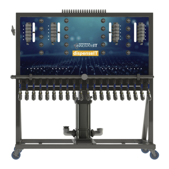
Page 5: System Overview
System Overview 2. System Overview The dispenseIT Chemical Delivery System is a reliable, automated chemical delivery solution designed to ensure precise and consistent mixing and application of cleaning chemicals in car wash systems. Its primary function is to automate the accurate dilution and distribution of chemicals, ensuring optimal performance for a wide variety of car wash applications. - Page 6 Fig. 2.1 - 1 - dispenseIT identification Fig. 2.1 - 2 - dispenseIT electrical enclosure dispenseIT Instruction Manual System Overview V 2.0, 10-31-24...
- Page 7 Table 2.1 - 1 - dispenseIT component features and functions Features/Functions Component Main Air Regulator - Adjusts system air pressure for appropriate valve operation Manifold - Supplies process water to function valves - Allows individual functions to be isolated during maintenance or trouble- Isolation Valves shooting without shutting down the entire system Process Valves/Solenoids...
-
Page 8: System Specifications
2.2 System Specifications Table 2.2 - 1 - dispenseIT specifications 5 HP - 30 GPM @ 200 psi Pump Output 7.5 HP - 40 GPM @ 200 psi Solution Output (Flow Rates) 0.3-15 GPM @ 200 psi 208VAC / 3PH Voltage (Pump) 480VAC / 3PH 17 A (208) -
Page 9: Installation
Installation 3. Installation Installation of the dispenseIT must conform to local plumbing, electrical, and sanitation codes. The customer is respon- sible for obtaining all permits and ensuring the following conform to all state and local codes before installing the dispen- seIT. -
Page 10: Installing Water Line
Air Output Air Supply To Tunnel To Regulator (1/2”) (3/8”) 60.5” 23” 64.375” 59.5” 69.375” Output To Manifold Main Water Inlet (5HP - 1.25”/ 7HP - 2”) Fig. 3.2 - 1 - 20 Function Floor Mount dispenseIT Air Supply Air Output To Regulator To Tunnel (3/8”) -
Page 11: Installing Air Line
2. Install water feed line to the inlet side of the pump using appropriate fittings for site hosing (Fig.3.2.1 - 1). Main Water Inlet (5HP - 1.25”/ 7HP - 2”) Fig. 3.2.1 - 1 - Water line connection 3.2.2 Installing Air Line 1. -
Page 12: Installing Liquid And Air Connections For Functions
3.2.3 Installing Liquid and Air Connections for Functions NOTE High Flow injectors (above 5 gpm) require ¾” process line. 1. Connect ½” liquid lines to the appropriate injector port as specified in your customer configuration form (Fig. 3.2.3 - 1). Fig. -
Page 13: Electrical Installation
3.3 Electrical Installation WARNING! Electrical installation to be performed by a qualified electrician. Follow all local codes. 3PH breaker power to be supplied by customer. The electrical schematics and connection points in the controller are designated in Appendix 4. 1. - Page 14 4. Connect the grounding conductor to the ground lug (Fig. 3.3 - 2). Fig. 3.3 - 2 - Pump grounding conductor and ground lug 5. Connect the 3PH power to the pump’s terminal strip (terminal wiring plug can pull out for wiring ease). Inspect to ensure the terminal plug is fully seated.
-
Page 15: Installing Injectors
NTS 1-11 TS 1-20 PTS 1 & 2 Fig. 3.3 - 3 - Electrical enclosure connection points 3.4 Installing Injectors The dispenseIT arrives with any High Flow injectors installed from the factory. Standard Flow injectors are shipped with the unit. Installation of Standard Flow injectors is done via provided quick connectors. 1. -
Page 16: Startup & Operation
Startup & Operation 4. Startup & Operation WARNING! Check and verify the tightness of all power distribution lines (screw terminals) before the startup process. NOTE Ensure all steps and precautions in Section 3 have been completed before starting up the dispenseIT. 4.1 Priming The Pump 1. -
Page 17: Pump Settings
9. When viewed from above, the pump should rotate counterclockwise. 10. To reverse the direction of rotation, first switch off the power supply. Interchange any two phases of the power supply. 11. Switch on the power again and check for proper direction of rotation. Once direction of rotation has been verified, switch off the power again. -
Page 18: Setting Foaming Functions
4.4.1 Setting Foaming Functions To effectively set up and adjust the foaming functions on the dispenseIT, use the air regulator knob to control the foam density and texture (Fig. 4.4.1 - 1). • Increase Foam Thickness: • If a thicker or denser foam is desired, increase the air supply to the mixture. To do this, turn the air regulator knob clockwise. -
Page 19: Service & Maintenance
Service & Maintenance 5. Service & Maintenance The best method to maintain the dispenseIT is to take a few minutes daily to examine the unit for leaks or any indication of a mechanical or electrical fault. If a change in performance or operation is observed, it is essential to take corrective action quickly to minimize the poten- tial damage to the system. -
Page 20: Troubleshooting
Troubleshooting Section Header Troubleshooting 6. Troubleshooting For product support, contact support@innovateITcarwash.com, or call (518) 741-4200 (option 2). Symptom Potential Causes Solution • Verify pump has constant voltage. Check any breakers, disconnect switches, and/or fuses • No 3PH power to pump. installed in the electrical system. - Page 21 Symptom Potential Causes Solution Verify items listed in ‘Pump Will Not Run’ section. • Pump is not running. • • Pump setpoint is too low. • Raise the pump setpoint to the desired pressure. Insufficient water supply to pump. • •...
- Page 22 Symptom Potential Causes Solution Manifold solenoid isolation ball Open the ball valve and verify water flow through • • valve is closed. the solenoid to the injector. No Water Flow Through • Isolate the solenoid. Disassemble the solenoid and check for debris. Injectors •...
-
Page 23: Recommended Spare Parts
Spare Parts 7. Recommended Spare Parts Below is a list of recommended spare parts that may require replacement during the course of system operation. innovateIT Product Number Description DS-REG-4-SMC Foaming Regulator 7303664 Process Air Valve DS-CV0074 Standard Flow Injector Check Valve DS-CV0072 High Flow Injector Check Valve 7903683... -
Page 24: Replacing Process Air Valve
5. Remove the elbows from the rear of the regulator (Fig. 7.1.1 - 1). 6. Unthread the capture nut on the regulator (Fig. 7.1.1 - 2). Capture Nut Fig. 7.1.1 - 2 - Regulator capture nut location 7. Remove regulator. 8. -
Page 25: Replacing Check Valve
1. Turn off the main air supply to the unit. 2. Close the ball valve on the selected function (Fig. 7.1.2 - 1). 3. Disconnect the quick connect fitting or unthread the high flow adapter depending on the type of function. 4. -
Page 26: Replacing Metering Tip
3. Unthread the check valve from the injector (Fig. 7.1.3 - 1). Push Connect Check Valve and Orientation Indicator Poly Tube Fitting Fig. 7.1.3 - 1 - Check valve replacement 4. Replace poly tube fitting onto the new check valve. 5. -
Page 27: Appendix 1 - System Identification
Appendix 1 - System Identification Component Component Air Regulator Main Water Input Manifold Manifold Pressure Gauge Shut-Off Valves Air Controls (1 Per Function) Solenoids Air Manifolds DEMA Rocket Injectors Electrical Enclosure Output to Manifolfd Air Output (To Tunnel) Grundfos VFD Pump dispenseIT Instruction Manual Appendix 1 V 2.0, 10-31-24... - Page 28 Injectors Adapter Quick Connect High Flow Injector Standard Flow Injector Check Valve (1/2”) Check Valve (3/8”) Hose Barb (3/4”) Poly Fitting (1/2”) dispenseIT Instruction Manual Appendix 1 V 2.0, 10-31-24...
-
Page 29: Appendix 2 - Injector Psi Flow/Dilution Data
Appendix 2 - Injector PSI Flow/Dilution Data dispenseIT Instruction Manual Appendix 2 V 2.0, 10-31-24... - Page 30 dispenseIT Instruction Manual Appendix 2 V 2.0, 10-31-24...
- Page 31 dispenseIT Instruction Manual Appendix 2 V 2.0, 10-31-24...
- Page 32 dispenseIT Instruction Manual Appendix 2 V 2.0, 10-31-24...
-
Page 33: Appendix 3 - Pump Programming
Appendix 3 - Pump Programming Pump Programming The Grundfos Pump arrives pre-programmed. In the event that the pump settings are reset—whether due to an accidental reset or maintenance requirement—follow the steps below to reprogram the pump with the factory-default settings provided by innovateIT. - Page 34 dispenseIT Instruction Manual Appendix 3 V 2.0, 10-31-24...
- Page 35 dispenseIT Instruction Manual Appendix 3 V 2.0, 10-31-24...
-
Page 36: Appendix 4 - Electrical Schematics
Appendix 4 Electrical Schematics 120v dispenseIT Instruction Manual Appendix 4 V 2.0, 10-31-24... - Page 46 Appendix 4 Electrical Schematics dispenseIT Instruction Manual Appendix 4 V 2.0, 10-31-24...
Need help?
Do you have a question about the innovateIT dispenseIT and is the answer not in the manual?
Questions and answers