
Summary of Contents for sinalda mSVS+ Series
- Page 1 mSVS+ ERIES USER / OPERATOR PRODUCT MANUAL AC VOLTAGE STABILISERS / REGULATORS 1 to 10kVA SINGLE PHASE WITH SECTIONS ON INSTALLATION, MAINTENANCE & FRONT-LINE FAULT FINDING...
-
Page 2: Please Read
The Manual should be read in full before attempting to use or operate the equipment. If any problems are encountered with the procedures contained within this Manual, then seek assistance from Sinalda UK or the distributor from whom you purchased the equipment. Whilst every precaution has been taken to ensure the accuracy and... -
Page 3: Table Of Contents
5.5 Cable Connections ………………………………………….……………… Commissioning ………………………...………………………………….………. 14 6.1 Pre-commissioning Checks …..…………………………………………. 14 6.2 Initial Power Up ……………………………………………………………… Operations ……………………………….………………………………….………. 15 7.1 Turning-On Procedure ……………………………………………………. 7.2 Turning-Off Procedure ……………….…………………………………… Bypass Operation ..…………………………..………………………….………. 16 mSVS+ SERIES – User/Operator/Product Manual Page SAUK-mSVS-2025-01 https://www.sinalda.com... - Page 4 10. Troubleshooting ………………………………………………………….………. 19-20 Appendices A1. Technical Specification ………………….………………………………………….. 21-22 A2. Recommended Spares …………….……………………………………………….. 23 A3. Main Control PCB: Component Placement ……………………………….. 24-25 A4. Adjusting System Parameters ……………………………………………….…. 26-27 A5, Product Warranty ………………………………….………………………..……….. 28-31 mSVS+ SERIES – User/Operator/Product Manual Page SAUK-mSVS-2025-01 https://www.sinalda.com...
-
Page 5: Introduction
At Sinalda, we work with companies and organisations all over the world to safeguard their electronic and electrical equipment against harmful voltage irregularities. -
Page 6: Design Topology
Transformer to alter the primary voltage of the Buck / Boost Transformer. 1.3.2 The underlying Buck / Boost topology ensures a cost-effective solution to providing a stable mains voltage supply as the Motorised Variable mSVS+ SERIES – User/Operator/Product Manual Page SAUK-mSVS-2025-01 https://www.sinalda.com... -
Page 7: Principle Of Operation
In addition, there are guiding relay contacts which reverse the polarity of the Variable Transformer output to either ‘Buck’ (reduce) or ‘Boost’ (increase) the supply voltage in the secondary of the Buck / Boost transformer. mSVS+ SERIES – User/Operator/Product Manual Page SAUK-mSVS-2025-01 https://www.sinalda.com... -
Page 8: Standard Features
Over & Under Voltage Protection Ability configure Voltage Stabiliser/Power Conditioner, if required, to shut down in the event of the incoming voltage supply going outside the normal input window. mSVS+ SERIES – User/Operator/Product Manual Page SAUK-mSVS-2025-01 https://www.sinalda.com... - Page 9 Bypass Switch A useful emergency feature which, in the unlikely event of a system malfunction, enables the bypassing of the electronic controls circuitry to provide power direct to the load. mSVS+ SERIES – User/Operator/Product Manual Page SAUK-mSVS-2025-01 https://www.sinalda.com...
- Page 10 Designed, manufactured and supplied to comply with leading international standards (including associated UKCA conformity regulations). Market Leading Warranty Market-leading ‘No Quibble’ standard RTB warranty provision with 3 years/36 months from date of shipment. mSVS+ SERIES – User/Operator/Product Manual Page SAUK-mSVS-2025-01 https://www.sinalda.com...
-
Page 11: Safety Instructions
Please save these instructions for future reference 2.1 Introduction These instructions are addressed to the Installer and End User / Operator of the mSVS+ Series of AC Voltage Stabiliser / Regulator. We strongly suggest you keep this manual next to the Stabiliser for future reference. -
Page 12: Symbol Warning Information
2.3 Symbol Warning Information The following symbols are used throughout this manual – Warning Information This symbol alerts you to important information. Electrical Hazard This symbol indicates an electrical hazard may be present. mSVS+ SERIES – User/Operator/Product Manual Page SAUK-mSVS-2025-01 https://www.sinalda.com... -
Page 13: Transport, Delivery, Storage & Unpacking
3.2.3 Should any damage be observed immediately notify the shipping agent / transport company involved with the shipping and inform Sinalda, or the resale partner from whom you purchased the equipment A detailed report including photographs of any damage observed will be required to support any indemnity / insurance claim. -
Page 14: Unpacking
fixings. 3.4.5 If any damage, as a result of shipping is observed immediately notify the shipping agent /shipping company and inform Sinalda, or the resale partner from whom the unit was purchased. 3.4.6 Do not install the Voltage Stabiliser if there is any sign of damage. -
Page 15: Position, Ventilation & Cooling
2% for each additional °C, up to a max of 60°C, and 2.5% for each additional 500 metres. 4.2.3 The temperature of the air entering the Voltage Stabiliser cabinet must not exceed the temperature shown above. mSVS+ SERIES – User/Operator/Product Manual Page SAUK-mSVS-2025-01 https://www.sinalda.com... -
Page 16: Ventilation & Cooling
Stabiliser. 4.2.6 DO NOT put anything on top of the cabinet or restrict the flow of air to and from the system. mSVS+ SERIES – User/Operator/Product Manual Page SAUK-mSVS-2025-01 https://www.sinalda.com... -
Page 17: Electrical Installation & Cabling
System Grounding 5.3.1 The safety of any Voltage Stabiliser depends upon proper grounding. Grounding primarily safety. Correct implementation grounding also enhances equipment performance. mSVS+ SERIES – User/Operator/Product Manual Page SAUK-mSVS-2025-01 https://www.sinalda.com... -
Page 18: Voltage & Load Checks
5.5.1 Connect the mains input supply to terminals marked INPUT (Li and Ni). Ensure that both the input and output earth cables are connected to the Ground/Earth terminal. 5.5.2 Connect the load to terminals marked OUTPUT (Lo, No) mSVS+ SERIES – User/Operator/Product Manual Page SAUK-mSVS-2025-01 https://www.sinalda.com... -
Page 19: Commissioning
Appendix A3 & A4 for calibration instructions. 6.2.6 Apply the load gradually ensuring that the indication on the front panel indicates the correct output voltage and that the load current increases as expected. mSVS+ SERIES – User/Operator/Product Manual Page SAUK-mSVS-2025-01 https://www.sinalda.com... -
Page 20: Operations
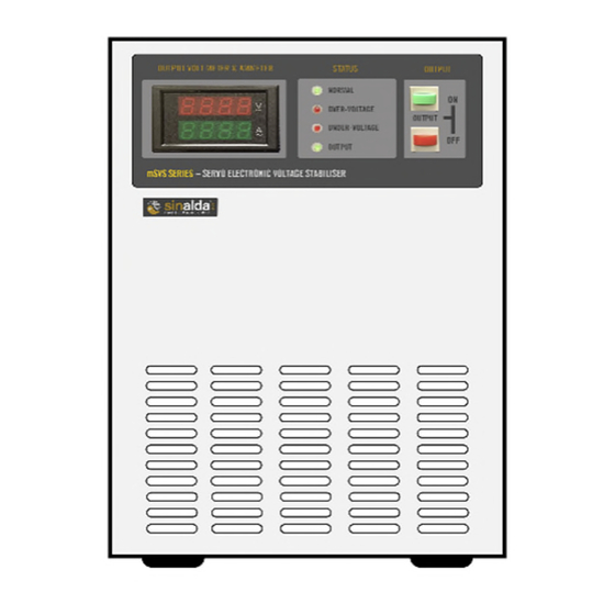
7.2.1 Power down / disconnect the electrical load equipment. 7.2.2 To disengage the output simply press the red ‘OFF’ button on the Front Panel. 7.2.3 Switch ‘OFF’ the input circuit breaker. Front View Rear View mSVS+ SERIES – User/Operator/Product Manual Page SAUK-mSVS-2025-01 https://www.sinalda.com... -
Page 21: Bypass Operation
8.2.3 Switch ON the Input Switch. The Stabiliser will cycle through its startup sequence to provide a regulated output. 8.2.4 To engage the output simply press the green ‘ON’ button on the Front Panel and reapply the load gradually. mSVS+ SERIES – User/Operator/Product Manual Page SAUK-mSVS-2025-01 https://www.sinalda.com... -
Page 22: Basic Maintenance & Servicing
1. Check to ensure that there are no apparent signs of damage to any of the components in the system. 2. Check all wiring connections to ensure none have worked loose. As required, tighten any loose connections. As Applicable mSVS+ SERIES – User/Operator/Product Manual Page SAUK-mSVS-2025-01 https://www.sinalda.com... -
Page 23: Output Voltage Adjustment
Voltage Stabiliser. If your site is subject to frequent high voltage surges, then it may be prudent to consider replacing the Surge Protection Devices on a more regular basis. mSVS+ SERIES – User/Operator/Product Manual Page SAUK-mSVS-2025-01 https://www.sinalda.com... -
Page 24: Troubleshooting
Upgrade the AVR capacity. current 2. Newly installed exceeds the equipment rated value Over 1. Fan Failure Shutdown the stabiliser and temperature 2. Overload replace the fan. Reduce loading level. mSVS+ SERIES – User/Operator/Product Manual Page SAUK-mSVS-2025-01 https://www.sinalda.com... - Page 25 Bypass power supply to provide power for the connected equipment, contact your local distributor ASAP. To enhance its service life and reduce the faults, please keep a clean and dried environment around the Voltage Stabiliser mSVS+ SERIES – User/Operator/Product Manual Page SAUK-mSVS-2025-01 https://www.sinalda.com...
-
Page 26: Appendices
1.5 x max. Current rating for 10 seconds Capability: Surge TVSS – Protects loads against high energy Spikes & Suppression: Transient Voltages Harmonic None introduced Distortion: Start Up Protects load equipment from damaging start up voltage Protection: surges mSVS+ SERIES – User/Operator/Product Manual Page SAUK-mSVS-2025-01 https://www.sinalda.com... - Page 27 Months (IP54 Models) from date of supply – with extendable option to 5 Years. Standard Input Switch / Breaker, Electronics Controls Bypass Features: Switch, Over / Under Voltage Indication, Time delayed Auto-Restart and Digital Metering mSVS+ SERIES – User/Operator/Product Manual Page SAUK-mSVS-2025-01 https://www.sinalda.com...
-
Page 28: A2. Recommended Spares
Output Contactor Motorised Variable Transformer For more detailed individual model spares listings and pricing, please contact the Service Department at Sinalda UK, or the resale partner from whom you purchased the equipment. Warranty Spares Availability For spares required under valid warranty claim situations, spares are supplied free of charge. -
Page 29: A3. Main Control Pcb: Component Placement
VR4: Switch Setup of Output Under Voltage Protection (-15% of Output Voltage) DIP SWITCHES DS1: Stability Adjustment of Output Voltage (Refer to the attached table) DS2: Operating Voltage Setup for Output Over / Under Voltage Protection mSVS+ SERIES – User/Operator/Product Manual Page SAUK-mSVS-2025-01 https://www.sinalda.com... - Page 30 LED of AVR “Voltage Increasing"(Yellow) LED of AVR "Voltage Decreasing (Yellow) LED of Over Voltage Protection (Red) LED of Under Voltage Protection (Red) LED of AVR Normal Operation (Green) LED of K2 Works (Yellow) mSVS+ SERIES – User/Operator/Product Manual Page SAUK-mSVS-2025-01 https://www.sinalda.com...
-
Page 31: A4. Adjusting System Parameters
The Adjustments VR1 (25 Turns): To adjust the Output Voltage of the Stabiliser, turn the potentiometer clockwise to raise the output voltage and counterclockwise to reduce the voltage. mSVS+ SERIES – User/Operator/Product Manual Page SAUK-mSVS-2025-01 https://www.sinalda.com... - Page 32 10 seconds. Options available are 2, 5, 10 and 15 seconds. NB: Only one switch can be selected. If no switches are selected there will be no delay on restart. mSVS+ SERIES – User/Operator/Product Manual Page SAUK-mSVS-2025-01 https://www.sinalda.com...
- Page 33 A5. CE/UKCA Declaration of Conformity mSVS+ SERIES – User/Operator/Product Manual Page SAUK-mSVS-2025-01 https://www.sinalda.com...
-
Page 34: A5, Product Warranty
Quality which fulfills the highest of requirements. 1.2 Subject to the limitations set out below, Sinalda warrants that the products will correspond with their specification at the time of despatch and will be free from defects in material and workmanship for a period of 3 year / 36 months for IP20 Models / 2 years / 24 months for IP54 models, from date of shipment. - Page 35 Goods or other use or resale by the Buyer, except as expressly provided in these Conditions. mSVS+ SERIES – User/Operator/Product Manual Page SAUK-mSVS-2025-01...
- Page 36 Power failure or breakdown in machinery. Extended Warranty – 5 Years As an option Sinalda offers an extended warranty option which, for a modest fee, extends the standard warranty cover to a full 5 years from date of supply. This extended cover will not only save you possible parts costs, but by priority access to our dedicated technical backup support staff...
- Page 37 A7. Installation, Commissioning, Service & Remedial Action Log A7.1 Installation & Commissioning Activity Date Performed by Notes / Ref No Installation Commissioning A7.2 Service / Routine Maintenance Date Performed by Notes / Ref No mSVS+ SERIES – User/Operator/Product Manual Page SAUK-mSVS-2025-01 https://www.sinalda.com...
- Page 38 A7.3 Remedial Action Date Performed by Notes / Ref No RA10 A11.4 Notes Ref No Notes mSVS+ SERIES – User/Operator/Product Manual Page SAUK-mSVS-2025-01 https://www.sinalda.com...
- Page 39 SERIES – User/Operator/Product Manual Page SAUK-mSVS-2025-01 https://www.sinalda.com...
- Page 40 3 to 800 Amps Volt Drop Compensators 3 to 1000 kVA Automatic Voltage Optimisers 10 to 100 kVA www.sinalda.com Copyright 2025 © Sinalda UK Limited reserve the right to change any or all the specifications indicated or implied without prior notice. E&EO...
Need help?
Do you have a question about the mSVS+ Series and is the answer not in the manual?
Questions and answers