
Related Manuals for Everfine EFCO EGL-6150

Summary of Contents for Everfine EFCO EGL-6150
- Page 1 EGL-6150 Gaming Logic System User Manual Version 1.1 JUL 2021 Published. Copyright©2021 EFCO. All rights reserved.
-
Page 2: Revision History
Revision History Revision Date Description 20-04-2021 First edition 01-07-2021 Update product specification... -
Page 3: Copyright Notice
Copyright Notice This document is copyrighted© 2021. All rights are reserved. The original manufacturer reserves the right to make improvements to the products described in this manual at any time without notice. No part of this manual may be reproduced, copied, translated, or transmitted in any form or by any means without the prior written permission of the original manufacturer. -
Page 4: Packing List
Packing List Before setting up your product, please ensure the following items have been included in the box: 1x EGL6150 1x Power cable If any of these items are missing or damaged, please contact your distributor or sales representative immediately. -
Page 5: Safety Instructions
Safety Instructions Please read the following safety instructions carefully. It is advised that you keep this manual for future references. 1. Make sure the power source matches the power rating of the device. 2. Always completely disconnect the power before working on the system’s hardware. 3. -
Page 6: Table Of Contents
Index Chapter 1 ............................1 Product Specification ......................... 2 Chapter 2 ............................5 Front Panel I/O ........................... 6 2.1 Display interface ......................6 2.2 USB ports ........................6 2.3 LAN ports ........................6 2.4 Serial ports ........................7 2.5 Audio ..........................7 2.6 LED indication....................... - Page 7 Chapter 7 ............................20 Chassis and Dimension ......................21 7.1 Top side ........................21 7.2 Front side ........................21 7.3 Rear side ........................21 7.4 Left side ........................22 7.5 Right side ........................22...
-
Page 8: Chapter 1
Chapter 1... -
Page 9: Product Specification
Product Specification Item Description AMD Ryzen™ Embedded R1305G Processor (2C/4T 1.5GHz, Boost to 2.8Ghz, L2= 1MB, L3=4MB, TPD =8-10W) Main Memory 1x DDR4 SO-DIMM socket, maximum to 16GB. Supports DDR4-2400. Integrated: AMD Radeon™ Vega 3, max. 1000MHz Display Maximum output support for 3 displays VGA port D-Sub 15. - Page 10 Backup Battery 1x Li-Ion Battery CR2032* 3V for system RTC 2x Li-Ion Battery CR2032** 3V for SRAM and EIT controller. Application SRAM data maintenance Intrusion logger Secure RTC *Battery life is over 5 years without system power supply **Battery life is longer than 300 days without system power supply Gaming I/O Hub Controller: GPC3800-E-B256...
- Page 11 LED strip controller 4x Independent LED strip controllers Supports 1 or 2-wire signals. Internal power support: +5V (default) / 2A. I/O on Board Edge 1x VGA D-Sub 15-pin display output 2x Video digital outputs 1x RJ45 dual USB 3.0 integrated connector ...
-
Page 12: Chapter 2
Chapter 2... -
Page 13: Front Panel I/O
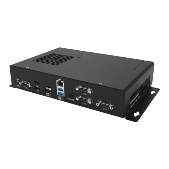
Front Panel I/O 2.1. Display interface One VGA D-Sub 15 + Two digital output 2.2. USB ports Two USB 3.0 + Two USB 2.0 2.3. LAN port One RJ45 (LAN1). Supports 10/100/1000Mbps Ethernet. 10Mbps/ 100Mbps/ 1Gbps Speed/ Activity LED Scheme LED A LED B (SPEED) -
Page 14: Serial Ports
2.4. Serial ports COM1 and COM2 are full RS232. COM4 is 4-wire RS232. COM1 pin#9 is 5V/12V selectable by JSETCOM1. Jumper Setting Description Open Pin9 on COM port is floating Jumper on 1-2 Pin9 on COM port is 12V supply(default) Jumper on 2-3 Pin9 on COM port is 5V supply 2.5. -
Page 15: Chapter 3
Chapter 3... -
Page 16: Rear And Side I/O
Rear and Side I/O 3.1. I/O Type description Type Description I-TTL TTL voltage level input I-ISO Isolation protected input O-OD Open-Drain output O-AA Amplified audio output signal Power or Ground 3.2. JAMMA 72-Pin connector Component Side(A) Definition Type Solder Side(B) Definition Type Pin# Physical... - Page 17 Door SW1 / INTR 0 / I-TTL/ DC +5V Power Slot One GPI_D0 I-ISO Slot Three GPI_B3 I-ISO Slot Two GPI_D2 I-ISO Bill Acceptor GPI_D1 I-ISO Clear Error GPI_C2 I-ISO Menu GPI_C0 I-ISO Button 14 GPI_B5 I-ISO Collect Button GPI_B4 I-ISO Hopper/Ticket-CT GPI_D3...
-
Page 18: Jumper Settings For Jamma Connector
3.3. Jumper settings for JAMMA connector. I/O Pin# Jumper# Jumper on 1-2 (default) Jumper on 2-3 JP_A15 GPI_C1 Bill Door SW (INTR 0) JP_A17 Door SW1 (INTR 0) DC +5V JP_A35 Attendant Lamp (GPO_C3) JP_A36 Speaker Right- JP_B23 Lamp 13 (GPO_B4) JP_B24 Meter 6 (GPO_C5) Serial Edge CTS... -
Page 19: Spi Connector
3.5. SPI connector Four SPI connector (JST 1x4 pin) support for LED strips. Pin # Description +5V (default) SPI_CLK SPI_MOSI Pin1 power is 5V/12V selectable by JSETCN21 to JSETCN24. Jumper Setting Description Open No power on pin1 Jumper on 1-2 Power on pin1 is 5V supply(default) Jumper on 2-3 Power on pin1 is 12V supply... -
Page 20: Chapter 4
Chapter 4... -
Page 21: Gpio Hardware Attributes
GPIO Hardware Attributes In general, the gaming devices such as Meter, Hopper, Coin acceptor, Bill acceptor and Key lock are contolled by GPIO. This helps the user focus on APP program development. Below is the descriptions of hardware behaviors. 4.1. O-OD (Open Drain Output) Each output pin on the golden finger is designed to be an open drain ouput. -
Page 22: Intrusion
4.3. Intrusion Provides power to the unit from either the system or auxiliary power port. The intrusion detection is controlled by the EIT controller. When the system power is turned on, the EIT operates via system power. Once the system power is turned off, the EIT power source will switch to the auxiliary power which is provided by a backup battery and the EIT will continue to operate. -
Page 23: Chapter 5
Chapter 5... -
Page 24: Electrical Characteristics
Electrical characteristics Electrical Characteristics Value Symbol Description Unit Min. Typ. Max. Isolation input logic high voltage V_I-ISO_H (not included Coin in , Bill in & Hopper sensor) V_I-ISO_L Isolation input logic low voltage -9.5 -- I_ISO_L Isolation input logic low current. V_O-OD_PH Open-Drain pull-high voltage I_O-OD... -
Page 25: Chapter 6
Chapter 6... -
Page 26: Quick Access Door
Quick Access Door 6.1 Introduction The mechanical design is a more convenient way to access the SATADOM when it needs to be replaced. 6.2 Installation and removal of the Quick Access Door Before the Quick Access Door can be removed, the user MUST switch off the external power source to prevent a circuit short and electrostatic discharge. - Page 27 Chapter 7...
- Page 28 Chassis and Dimension 7.1 Top side 7.2 Front side 7.3 Rear side...
- Page 29 7.4 Left Side 7.5 Right side End of Document...
Need help?
Do you have a question about the EFCO EGL-6150 and is the answer not in the manual?
Questions and answers