Advertisement
BELL SYSTEM PRACTICES
Station
Operations
Manual
Minor
Station
Systems
SECTION C53.
903
Issue
A, December
1956
The B.T.
Co.
of Canada
Provisional
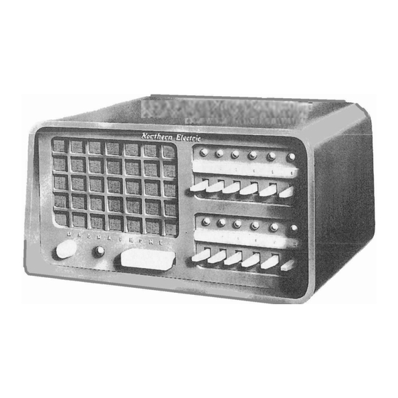
LOUDSPEAKING INTERCOMMUNICATION EQUIPMENT
SENIOR MAG NA PHONE ( NORTHERN ELECTRIC CO. )
1. GENERAL
1.01
This
section
is
issued
to
provide
installation
and maintenance
infor-
mation
until
a comprehensive
practice
can
be written.
1.02
This
section
will
consist
of:
(a)
A General
Section.
(b)
The
Manufacturer's
Instruction
Bulletin,
Senior
Mae;naphone
SH6A
SM12A.
1.03
General
Section
C5J.900
applies
to
this
equipment
and should
be
read
before
proceedins
with
this
Section.
1.04
Extension
units
EX12A and EX24A
are
not
being
standardized
and will
not
be
available
for
requisition.
Where
a
master
station
is
required
for
connection
to
more
than
12
other
stations,
order
equipment
in accordance
with
Table
I.
Connected
Station
No.
13-24
25-36
37-48
TABLE I
Unit
Station
Master
Magnaphone
Code
SM24B
SMJ6B
S!'148B
1.05
Where
a 6 station
or
12
station
master
station
is
required
for
a
25 cycle
area,
use
the
SM12B. Equipment
for
more
than
12 stations
in a 25 cycle
area
can be provided
as
a
special
assembly.
·
1.06
A kit,
nameplate,
Rl9412-24,
consist-
ing
of a
moulded
lucite
nameplate
with
the
name "The Bell
Telephone
Company
of Canada"
in
three
dimensional
letters,
and
two
nickel
self-tapping
screws,
is
available.
This
nameplate
shall
be affixed
over
the
name
"Northern
Electric"
on
the
face
of substation
and master
stations.
To
install
·the
nameplate,
punch
out with
some
sharp
instrument
the
thin
wall
of material
in the
punch-out
holes
in
the
cabinet
on
either
side
of the
name "Northern
Electric".
Place
the
nameplate
and screw
in the
s~lf-
tapping
screws.
1.07
A
screwdriver,
Phillips,
size
No,
1,
blade
length
required
for
the
installation
equipment.
of
point
3
inch
is
of
this
1.08
While
most
of the
wiring
consists
of
connecting
the
cable
at
the
terminal
strips,
it
is
necessary
to
make modifications
to
the
wirins
inside
the
chassis.
The
following
modifications
may be made:
(a)
Conversion
of
station
selector
keys
from master
station
to substation
use,
Instruction
Bulletin,
Page 9.
(b)
Conversion
of
station
selector
keys
from
substation
to master
station
use,
Instruction
Bulletin,
Page 9,
(c)
The
removal
of
straps
on
terminal
strip
TSl
on the
Amplifier
Chassis,
and the
connection
of the
four
conductors
from
handset
attachment,
Rl97256A,
Instruction
Bulletin,
Page 15.
(d) The
modification
of
the
wiring
of
station
key for
connection
to the
pre-
selected
all-call
relay
unit,
Instruction
Bulletin,
Page
17,
(e)
The modification
of a station
key for
the
long
line
remote
control
relays
per
Rl9807A.
(Covered on Drawing Rl9807-7
).
1.09
Both
long
line
relays
and
all-call
relays
may be used
on the
same master.
1,10
Adjust
the
volume
in accordance
with
instructions
in
the
Instructions
Bulletin
on Page
6.
A kit,
volume
control
per
Rl9109-60
is
available
for
use
in ad-
justing
the
volume
at
the
substation.
Install
it
in accordance
with
the
informa-
tion
supplied
with
it.
1.11
Instruct
the
customer
in
operating
the
equipment
in accordance
with
the
operating
instructions
on
tear-out
sheet,
pages
25 and 26, of the
Instruction
Bulletin.
Tear
out
the
above
pages
from
the
Instruc-
tion
Bulletin
supplied
with
the
station
and
leave
it
with
the
customer,
Destroy
the
bulletin
to prevent
it
getting
in company
files.
Page 1
1 Page
Advertisement
Table of Contents

Need help?
Do you have a question about the SENIOR MAGNAPHONE and is the answer not in the manual?
Questions and answers