Advertisement
MTR3B V4 Currahee Version
Mountain Topper
"The original Miniature QRP Transceiver"
Updated:
1/20/25
Firmware Version: 1.06 and higher
* Important – Read Manual Addendum for notes on Firmware Updates
Features
Bands: 40M, 20M, 15M
Power out: 5 typical at 13.8V Supply
Power & SWR Readout
Minimum detectable signal: ~0.1 uV
Push button operation
Color display
Real Time Clock
Five (5) 62 character CW message memories
Nine (9) Frequence memories per band
Adjustable Volume Control
Adjustable Side Tone
Specifications
Unit Weight: 5.72oz (133.8g)
Dimensions: 3.90"L x 2.625"W x 1.09"T (99.88mmL x 66.25mmW x 28.6mmT)
Display Dimensions: 1.06" x 1.04" (27mm x 26.3mm)
Internal Battery: CR2032 (supplied at purchase, replaceable with common brand)
Advertisement
Table of Contents

Related Manuals for LNR MTR3B V4 Currahee Version

Summary of Contents for LNR MTR3B V4 Currahee Version
- Page 1 MTR3B V4 Currahee Version Mountain Topper “The original Miniature QRP Transceiver” Updated: 1/20/25 Firmware Version: 1.06 and higher * Important – Read Manual Addendum for notes on Firmware Updates Features Bands: 40M, 20M, 15M Power out: 5 typical at 13.8V Supply Power &...
-
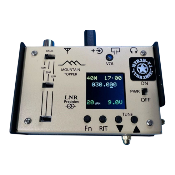
Page 2: Display Definitions
Display Definitions TIME BAND OP-Frequency CURRENT FUNCTION RIT delta frequency +00.000 when enabled CODE SPEED Supply Voltage Display is organized in 5 lines. * Lines 1 and 2 always display the same information. Operating band, time, and operating frequency. * Lines 3 and 5 change depending on the currently selected function. Operation Band Selection: •... -
Page 3: Frequency Tuning
Frequency Tuning: The single step tuning rate is set to 50 Hz per “Tap” of the Tune Up or Tune Down button. Fast Tuning: • If the [Tune Up] or [Tune Down] switch is held down for more than 500 ms, fast tune mode will activate. - Page 4 • HOLD [Fn] for 3 seconds. Note: This mode is NOT available while in straight-key mode. 23:59 030.000 Current function K-MEMORY EM X Exit Enter Message • Tap [EM](Fn) to start the enter message mode. • Tap [X](RIT) to exit the mode. •...
- Page 5 To access Frequency Memory: • HOLD [Fn] for 1 second o There are 9 memory locations available for each band. Op-Frequency 23:59 Current Memory Contents of selected location location selected 030.000 empty Current enabled function 1 F-MEMORY EN R/S (LD) Enter Toggle between recall and store •...
- Page 6 o To Pause, close the Dash paddle. Receive will be restored as long as the paddle is held closed. o The paddle state is detected between letters. 00:00 030.000 Memory Location Current function SEND MSG M0 X M1 M2 Exit •...
- Page 7 • The clock numbers turn to indicate set minutes mode. • Set Minutes: o Set the minutes to current time +1 minute. [Tune Down] increments the 10’s digit. [Tune Up] increments the 1’s digit. o Tap [E] (Fn/Keyer) o Set Hours: ...
- Page 8 Straight key mode: • SWR and power output is shown on the bottom line of the display while transmitting in straight key mode [1.0 SWR 5.0 W] • Straight key mode can be enabled two ways: o Automatic – use a MONO plug in the key jack (ground Dash input). This must be inserted when the power is off.
- Page 9 If your unit is below version 1.06, it is recommended that you update the unit. LNR Precision will perform these updates free of charge for customers wishing to update their unit. If you wish to receive an update of your unit, please write a...
- Page 10 Firmware 1.08 Version update: This is a software only update and adds CW Message Beacon Mode and Direct Frequency Entry (DFE). Should be considered optional and only needed if you desire these features. CW Message Beacon mode: The enable beacon mode: 1.
- Page 11 Should be considered optional and only needed if you desire these features. Note: may require extra time for LNR to return unit as it requires disassembly and component changes and new trace on PCB.
Need help?
Do you have a question about the MTR3B V4 Currahee Version and is the answer not in the manual?
Questions and answers