Advertisement
Overview
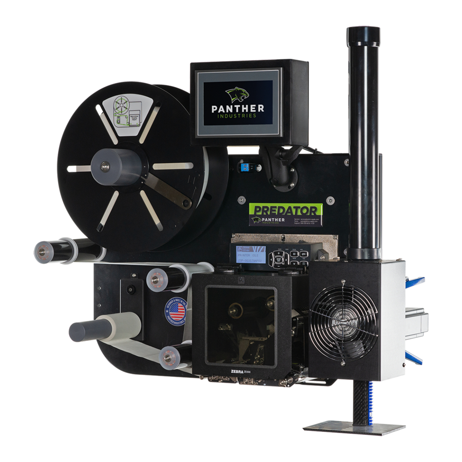
This document describes the steps to take to perform preventative maintenance and adjustment of the applicator assembly on your Panther Predator labeling automation system.
For any additional questions, please contact Panther's service and support department via telephone or email, shown below.
CONTACT US
8990 Barrons Blvd
Highlands Ranch, CO 80129, United States
P: 1-888-530-6018
E: Panther. Service@ProMachBuilt.com
Procedure
DISASSEMBLING APPLICATOR
To Disassemble Your Applicator Assembly:
- Remove the six (6) 10-32 x 1/4" button head screws holding the fan shroud in place.

- Remove fan shroud and disconnect the power wires from the fan.

- Loosen the four (4) 1/4-20 x 1/4" mounting bolts on the applicator motor.

- Slide the applicator motor and gear away from the applicator rack.

- Check that the gear is securely tightened onto the motor shaft. The gear is held securely in place with set screws located on the collar of the gear.
Note: Previous versions of the of the gear features two (2) 1/4" - 20 x 3/8" set screws located on the collar. Updated versions feature one (1) socket head 8/32 x 1/2" set screw located on the collar.

These set screws should be tightened onto the center of these flat spots. Thread lock may be used to prevent these set screws from coming loose over time. The gear should be positioned such that the teeth of the rack are centered on the teeth of the gears. Note: The motor shaft has two (2) keyed flat spots.
![]()
- Using even pressure on the motor, push the applicator drive motor back towards the applicator rack.Note: The motor should not be overly tight against the applicator rack. If the motor and gear are meshed too tightly, the applicator may short stroke.

- Tighten the four (4) 1/4 - 20 x 1 1/4" mounting bolts to secure the motor in place.

- Move the applicator rack up and down to ensure the motion is smooth and does not stall in any location. Check the applicator rack for any broken or damaged teeth. Clean any debris or build up within the teeth.
- Check the six (6) bearings on the applicator rack guide. Ensure all spin freely and are not broken. Replace as necessary.
- Check the location of the applicator home sensor. Remove the M8 power cable from the back of the sensor, then loosen the jam nut on the applicator home sensor. Turn the applicator home sensor in until it contacts the applicator rack. Loosen it by a half turn, then tighten the jam nut. Reconnect the M8 power cable.


OPTIONAL ADJUSTMENT - APPLICATOR POSITIONING
Over time, your applicator may move out of position. When servicing your applicator, we encourage you to check that the applicator head is in the following recommended position. The information on the subsequent pages picks up immediately following the preventative maintenance steps 1-10 above.
To Adjust the Applicator Assembly:
- The applicator should be positioned so that the tamp head is approximately 1/8" away from the print engine peel bar. You may adjust the horizontal distance by loosening the two (2) 3/8 - 16 x 2 1/2" mounting bolts, located adjacent to the rack guide.

- Loosen the vertical adjustment lock handles, located on the back of the Predator main plate.

- Adjust the vertical position of the tamp head so that the print engine peel bar splits the bevel on the tamp head.Note: This well require adjusting the fixed mounting bolt that the slide assembly rests on. You should position the surface of the tamp head approximately 1/16" below the position where the labels feed out.

- Slide the applicator assembly unit until it comes in contact with the home location bolt.
- Re-tighten the vertical adjustment lock handle.
- Re-connect the power wires to fan.
Note: Before reconnecting the fan, it is recommended that you clean the fan and fan base of any buildup of dust or debris. This can be done with isopropyl alcohol wipes or with compressed air, using the proper safety precautions. - Remount the fan shroud.
- On the Predator HMI display, press the [RESET] button, then press the [APPLY] button. Ensure the applicator cycles smoothly.


RECURRING MAINTENANCE AND CLEANING
Panther Industries recommends the fan shroud be removed and that the positioning of the applicator gear, and tamp head be checked on a regular basis. Please view the following video for recurring preventative maintenance on your Panther Predator labeling automation system.
Click video preview below or view at: https://www.youtube.com/watch?v=oRU2kIgANjs
Documents / Resources
References
Download manual
Here you can download full pdf version of manual, it may contain additional safety instructions, warranty information, FCC rules, etc.
Advertisement
Need help?
Do you have a question about the PREDATOR and is the answer not in the manual?
Questions and answers