Advertisement
Quick Links
Sinkiwskij
Peter
Date: 2024.11.28 11:13:57 -05'00'
Digitally signed by Peter Sinkiwskij
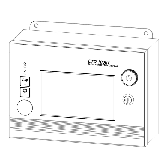
ETD1000T REMOTE ELECTRONIC TANK DISPLAY
TMS SERIES TANK MANAGEMENT SYSTEMS
This document describes the installation, configuration, and operation of the ETD1000T Remote
Electronic Tank Display with 7" Color Touchscreen, which is designed for use with any TMS2000,
TMS3000, TMS3000E, TMS4000, or TMS4000M Tank Management System.
72013 – ETD1000T Instruction Manual.docx
INSTRUCTION MANUAL
WITH 7" COLOR TOUCHSCREEN FOR
References V10.01 Firmware
PHONE: (631) 293-8450
FAX:
(631) 293-8533
www.pneumercator.com
November 28, 2024
Advertisement

Summary of Contents for PEI Pneumercator ETD1000T
- Page 1 Peter Sinkiwskij Digitally signed by Peter Sinkiwskij Date: 2024.11.28 11:13:57 -05'00' PHONE: (631) 293-8450 FAX: (631) 293-8533 www.pneumercator.com INSTRUCTION MANUAL ETD1000T REMOTE ELECTRONIC TANK DISPLAY WITH 7” COLOR TOUCHSCREEN FOR TMS SERIES TANK MANAGEMENT SYSTEMS References V10.01 Firmware This document describes the installation, configuration, and operation of the ETD1000T Remote Electronic Tank Display with 7”...
- Page 2 Page Intentionally Left Blank 72013 – ETD1000T Instruction Manual.docx November 28, 2024...
- Page 3 TABLE OF CONTENTS Page Section 1.0 PRODUCT OVERVIEW ..................4 TMS Compatibility....................5 Display Data ......................6 Tank Data – Meters and Bar Graphs ..............6 1.3.1 Configuring Tank Data Format ................7 1.3.2 Configuring Meters ....................8 1.3.3 Display Messages....................9 Sensor Data.......................
- Page 4 1.0 Product Overview The ETD1000T Electronic Tank Display panel is used in applications where it is desired to view TMS series tank management data from various on-site locations at distances up to 4000 feet (1200M) away from the main console. Since the ETD1000T is a microprocessor-based, addressable device communicating over the TMS RS-485 Peripheral Expansion Bus, up to 16 ETD1000T panels may be connected to a single TMS.
- Page 5 COVER INSIDE VIEW BOX INSIDE VIEW (NOT ALL FEATURES ARE SHOWN TO SCALE) (NOT ALL FEATURES ARE SHOWN TO SCALE) FRONT COVER HARNESS CONNECTOR ON/OFF SWITCH FUSE HOLDER +12V ETHERNET AND USB USB CONNECTORS MAIN BOARD CONNNECTOR LEDS (SIDE VIEW) LINE TERMINATOR SWITCH TERM...
- Page 6 1.2 Display Data The Color Touchscreen LCD provides the Tank and Sensor data in a manner consistent with Color Touchscreen TMS Models. Details are provided on the following pages. 1.3 Tank Data – Meters and Bar Graphs Tank Meters are shown above the optional bar graph section. Each Meter and common bar graph are configured on the LCD using a method comparable to an LCD TMS.
- Page 7 1.3.1 Configuring Tank Data Format Tap the Display button , then SETUP to access the settings screen providing choices for Number and Size of Meters and Bar Graphs as follows: Large Meters Small Meters Bar Graph Full Height Full Height Half Height Half Height Half Height...
- Page 8 Tap on the FORMAT tab at the top of the screen. The current selection is highlighted in green with the second bar selection shown as the checked box. The above example shows that 6 small meters and the large bar graph with the Second Bar Graph representing Water have been selected. If no Second Bar Graph is selected, only the Product Bar Graph will be visible.
- Page 9 Tap on the right edge of the Meter to view the list of available Units of Measure. Gross Volume in Gallons is shown selected above as indicated by the Blue Circle. 1.3.3 Display Messages The Meters on the LCD display will also represent select Alarms, Errors, and Statuses. Alarms are visible in the bottom left corner of each meter.
- Page 10 1.4 Sensor Data Tap the Display button , then SENSORS button to view the individual Sensor Statuses. Note: TMS2000 and TMS3000 systems do not support individual Sensor Statuses on the ETD1000T. Only Leak Sensors associated with an enabled Tank Channel will be represented as a LEAK alarm with a Red Background in the bottom left corner of the Meter.
- Page 11 Tapping on the ALL button provides the status for all sensors enabled in the TMS AND in the ETD1000T. The colored circles represent the following sensor statuses: Green: Normal. No Alarm or activity Red: Alarm or Active Sensor Yellow: Sensor Fault including Open or Short Circuit or invalid LLP configuration Gray: Absent Sensor Card Tap on a Small Sensor Panel to view a Large Sensor Panel containing a detailed description of the Sensor Status plus the Association with either a Tank or Dispenser Pan.
- Page 12 Tap on the Alarms button to show only Sensors with Statuses that are not Normal (Green) 1.5 Audible Annunciator A front panel audible annunciator is provided both to annunciate tank or communications alarm conditions, and as an audible confirmation aid when navigating using the membrane pushbuttons. Under alarm conditions, the beep rate of the annunciator varies with the alarm type as follows: Alarm Beep Rate...
- Page 13 2.0 Installation The ETD1000T is designed for both indoor and outdoor installation. If the unit is to be installed outdoors, the installer must pay attention to local code requirements for outdoor conduit runs containing AC line voltage. WARNING! This device is designed for Ordinary Location, Non-Hazardous installation only, as defined by Underwriters Laboratories (UL) and the National Electrical Code (NEC).
- Page 14 APPLICATION REVISIONS STANDARD WALL-MOUNT NEXT ASSY USED ON DESCRIPTION DATE APP. SEE REVISION SHEET FOR THIS AND OTHER REVISION (SEE OPTIONAL PANEL-MOUNT ON SHEET 2; DRYWALL-MOUNT ON SHEET 3) 11/11/24 HISTORY 10 15 4 11 16 [278] 16 [118] 9 7 8 [251] 4 1 4 [108] (4) Ø...
- Page 15 APPLICATION REVISIONS OPTIONAL PANEL-MOUNT NEXT ASSY USED ON DESCRIPTION DATE APP. SEE REVISION SHEET FOR THIS AND OTHER REVISION (SEE STANDARD WALL-MOUNT ON SHEET 1; DRYWALL-MOUNT ON SHEET 3) 11/11/24 HISTORY PANEL-MOUNT CUTOUT 12 7 8 [327] 1 7 16 [36] (SCALE 1:1) 12 1 8 [308] 10 15...
- Page 16 APPLICATION REVISIONS OPTIONAL DRYWALL-MOUNT NEXT ASSY USED ON DESCRIPTION DATE APP. SEE REVISION SHEET FOR THIS AND OTHER REVISION 11/11/24 (SEE STANDARD WALL-MOUNT ON SHEET 1; PANEL-MOUNT ON SHEET 2) HISTORY DRYWALL-MOUNT FRAMING 1 7 16 [36] (SCALE 1:1) 12 1 8 [308] 8 [327] 10 15 6 1 16 [154]...
- Page 17 2.2 Wiring 2.2.1 AC Power DANGER! AC power must be turned off at the circuit breaker before attempting to connect AC wiring to this device. WARNING! Do not connect or disconnect cable between Processor Board and Main Board or remove protective cover from Processor Board while AC power is applied.
- Page 18 2.2.2 Communications The ETD1000T supports an RS-485 multi-drop cabling topology as illustrated in Figure 2.2.2-1 below. Maximum cable distance from the TMS console to the furthest ETD1000T is 4000 feet (1200M). END-OF-RUN ETD1000/ETD1000T/RA400 ETD1000/ETD1000T/RA400 ETD1000/ETD1000T/RA400 (ETD1000 SHOWN) (ETD1000T SHOWN) (RA400 SHOWN) RA 400 REMOTE ANNUNCIATOR ETD 1000...
- Page 19 2.2.2.2 ETD1000T Terminal Connections A Plug-in terminal block is provided for connection to the RS-485 TMS Expansion Bus. Both input and output terminals are provided to support multi-drop wiring to additional ETD1000Ts or other TMS expansion bus peripherals. 2.2.2.3 ETD1000T Communications Wiring Detail END-OF-RUN ETD1000T ETD1000T...
- Page 20 TMS3000 SERIES TMS2000 SERIES TMS3000E SERIES TMS2000A SERIES TMS4000 SERIES TMS2000W SERIES TMS4000W SERIES TMS4000M SERIES CH. A (WHT/BL) CH. A (WHT/BL) CH. B (BL/WHT) CH. B (BL/WHT) SHD (SHIELD) SHD (SHIELD) 1/2" NPT 3/4" NPT 3/4" NPT FITTING AND FITTING AND FITTING AND CONDUIT...
- Page 21 3.0 Configuration The ETD1000T provides user-programmable features that allow the operator to alter display and audible alarm operation as well as control interaction with the TMS for remote alarm acknowledgement. These features are configured through the color touchscreen. No programming is required at the TMS console.
- Page 22 3.1 On-Board Programming 3.1.1 Setting Logical Address The TMS series console has the ability to individually address up to sixteen (16) ETD1000T/ETD1000 remote displays. The Logical Address for the ETD1000T is configured via the color touchscreen. Note that address order is not important but must be unique for every ETD connected to the same TMS. Note: The current ETD1000T firmware version and release date is shown at the bottom.
- Page 23 3.1.2 Tank Channel and Alarm Enable The ETD1000T may be configured so that only select Tanks and Alarms may be displayed on the ETD. This programming only affects the ETD and has no effect on other ETD units or the TMS. 3.1.2.1 Tank Channel Enable Tap on the TANKS tab, then SELECT tab to view the above screen.
- Page 24 3.1.2.2 Tank Alarm Enable Tap on the TANKS tab, then ALARMS tab to view the ALARMS screen. Check the boxes representing the alarms that should be represented on the ETD. Note that this screen will vary based on which TMS Model and Firmware is connected to the ETD.
- Page 25 3.1.3 Sensor Channel Enable TMS3000E, TMS4000, and TMS4000M with firmware V10.102 and higher The ETD1000T configuration allows for the Sensor data to be filtered so that only select sensors will be displayed on the ETD. Note: This screen is only visible for the above-listed models. If the Sensors tab is grayed out, the TMS cannot provide sensor-specific data to the ETD.
- Page 26 3.1.4 Audible Alarm Settings Tap on the SOUND tab to view the above screen Audible Alarm Enable: If DISABLED, audible will not activate for any condition and all of Audible Alarm Settings will not be displayed as they do not apply. Remote Acknowledgement: The TMS Internal Horn will be acknowledged when the ETD1000T Internal Horn is acknowledged, when enabled.
- Page 27 4.0 Front Panel Operation – Operator Mode ETD1000T Quick Reference Guide – Tank Alarms* Meter Display Mode Includes SetPoints (SP) for Product, Temperature Uncompensated Temperature Uncompensated Water, and Temperature plus Leak – – Volume (Barrels) Volume (Gallons/Liters) (Failed In-Tank Leak Test) Temperature Compensat e d Temperature Compensated –...
- Page 28 5.0 Product Specifications Dimensions: 10.9” W x 9.1”H x 4.7”D (277 mm x 230 mm x 118 mm) Weight: 11 lbs (5 kg) Operating Temperature: -22º to +160º F (-30º to +70º C) Humidity: 95% Non-condensing Enclosure Rating: Locking NEMA 12 (IP52), or NEMA 4X (IP66) (304 SS) Enclosure Mount Options: Wall-Mount (Standard) Panel-Mount (Optional), or Drywall-Mount (Optional)
Need help?
Do you have a question about the Pneumercator ETD1000T and is the answer not in the manual?
Questions and answers