Advertisement
Quick Links
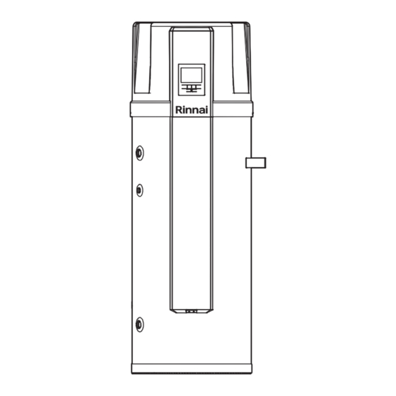
SHIMANTO 200 (EHP-WH200) - SHIMANTO 300 (EHP-WH300)
SHIMANTO 200 1A (EHP-WH200-1A) - SHIMANTO 300 1A (EHP-WH300-1A)
SHIMANTO 200 2A (EHP-WH200-2A) - SHIMANTO 300 2A (EHP-WH300-2A)
Sanitary water heat pump with water tank
User and installer manual
Rinnai_Shimanto200-300_EN.indd 1
Rinnai_Shimanto200-300_EN.indd 1
Models:
12/01/2021 12:33:22
12/01/2021 12:33:22
Advertisement


Need help?
Do you have a question about the SHIMANTO 200 and is the answer not in the manual?
Questions and answers