Advertisement
Quick Links
LIGHTING CONTROLS
MLSUC500 / 1250 Series
Embedded controller/webpage server for remote monitoring of MLS lighting systems
1. CONTENTS
Module: Qty 1
Storing instructions:
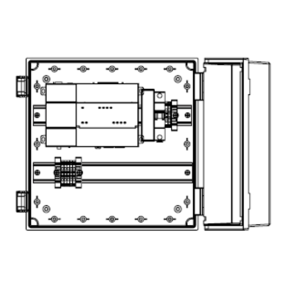
2. INSTALLATION
Mounting requirements
Copyright © 2024 Honeywell International Inc.
Installation and Mounting Instructions
Important: Retain these instructions.
These instructions shall be used by trained service
personnel only. If the equipment is used in a manner not
specifi ed by these instructions, the protection provided by
the equipment may be impaired.
Ensure that the enclosure keeps the MLSJ8 within its
required operating temperature range (considering a
24-watt dissipation).
Do not mount the unit:
- in an area with excessive moisture, corrosive fumes,
or explosive vapours.
- where vibration or shock is likely to occur.
- in a location subject to electrical noise.
1
32340084-001
Advertisement

Related Manuals for Honeywell MLSUC500 Series


Summary of Contents for Honeywell MLSUC500 Series
- Page 1 Do not mount the unit: - in an area with excessive moisture, corrosive fumes, or explosive vapours. - where vibration or shock is likely to occur. - in a location subject to electrical noise. 32340084-001 Copyright © 2024 Honeywell International Inc.
- Page 2 MLSUC500 / 1250-Installation and Mounting Instructions 2. INSTALLATION (continued) 1) Mount the MLSUC500 / 1250 The MLSUC500 / 1250 can be wall mounted by fi xing the supplied wall mounting lugs to the corner holes on the rear side as described in the supplied enclosure fi...
- Page 3 MLSUC500 / 1250 - Installation and Mounting Instructions 3. INSTALLATION (continued) 3) Connect Ethernet 4) Connect MLS Spine The MLSUC500 / 1250 assumes the role of Bus Master on the MLS Spine. This means that all the RB2000s should be given consecutive, unique non-zero addresses, refer to RB2000 documents.
- Page 4 Zone identities. Such as room names or numbers. • LCM locations • Emergency Ballasts Some of this information might only be available from those who commission the MLS lighting control system which may or may not be a Honeywell Commissioning Engineer. 32340084-001...
- Page 5 MLSUC500 / 1250 - Installation and Mounting Instructions TECHNICAL DATA Field Maintenance MLSUC500 / 1250 requires no routine maintenance. Dimensions and Clearance (including optional expansion modules) 32340084-001...
- Page 6 • Do not burn the device. By using this Honeywell literature, you agree that Honeywell will have no liability for any damages arising out of your use or modification to, the literature. You will defend and indemnify Honeywell, its affiliates and subsidiaries, from and against any liability, cost, or damages, including attorneys’ fees, arising out of, or resulting from, any modification to the literature by you.
Need help?
Do you have a question about the MLSUC500 Series and is the answer not in the manual?
Questions and answers