
Related Manuals for CPS DBA02-US-800

Summary of Contents for CPS DBA02-US-800
- Page 1 Installation and Operation Manual for DBA02-US-800 Breaker Box For SCH350KTL-DO/US-800 Inverters CHINT POWER SYSTEMS AMERICA CO., LTD. Rev 1.2 Jan., 2025...
- Page 2 Table of Contents Table of Contents Preface ..................4 IMPORTANT SAFETY INSTRUCTIONS ........5 Warnings and Symbols in this Document ........... 5 Markings on the Product ................7 Safety Instructions of Operating the Breaker Box ........9 General Introduction ..............11 Overview of Grid-tied PV system .............
- Page 3 Table of Contents 5.1.1 Check before Closing Breaker ............39 5.1.2 Close Breaker .................. 40 5.1.3 Open Breaker .................. 40 Maintenance ..................... 41 5.2.1 Regular Inspection ................41 5.2.2 Replace Fuse and Surge Protective Device (SPD) ......41 Technical Data ................44 Breaker Box Technical Data ..............
- Page 4 Please keep this user manual on hand for quick reference. Copyrights CPS reserves all rights in this manual. Any reproduction, disclosure or copy in whole or in part is forbidden without prior written authorization. CPS doesn’t accept any responsibility whatsoever for potential errors or possible lack of information in this document.
- Page 5 (SAVE THESE INSTRUCTIONS) Please read this user manual carefully before the installation and operation of this product. CPS reserves the right to refuse warranty claims for equipment damage if users fail to install the equipment according to the instructions in this manual.
- Page 6 IMPORTANT SAFETY INSTRUCTIONS NOTICE! NOTICE indicates a hazardous situation which, if not avoided, could result in equipment working abnormally or property loss. AVIS! indique une situation dangereuse qui, si elle n'est pas évitée, pourrait entraîner un fonctionnement anormal de l'équipement ou la perte de biens.
- Page 7 IMPORTANT SAFETY INSTRUCTIONS Markings on the Product Symbol Meanings HIGH VOLTAGE: This product works with high voltages! All work on the device must only be performed by qualified personnel as described in this document. Haute pression! Le produit convient aux environnements à haute pression! Tout le travail sur l'appareil ne peut être effectué...
- Page 8 IMPORTANT SAFETY INSTRUCTIONS WARNING For continued protection against risk of fire, replace only with same type and ratings of fuse. Refer to instruction manual for details. ATTENTION Pour continuer d’assurer la protection contre les risques d’incendie, il faut remplacer les fusibles de même type et courant. Reportez-vous au manuel d’instructions pour plus de detéils.
- Page 9 IMPORTANT SAFETY INSTRUCTIONS Safety Instructions of Operating the Breaker Box DANGER! Touching the wiring terminals inside the device may result in death by electric shock. DO NOT touch the terminals or conductors connected with PV modules or PV inverters, which may result in death by electric shock.
- Page 10 The device nameplate contains important information of the device, such as model, serial number and detailed parameters. If there is any problem or malfunction of the device during operation, please contact CPS customer Service and provide the serial number. Please keep the nameplate intact.
- Page 11 Inverter 800V/HV 2:1 Breaker Box Switch Box Figure 2-1 Application scenario of DBA02-US-800 The 2:1 breaker box includes two circuit breakers for overcurrent protection of up to two CPS SCH350KTL-DO/US-800 string PV inverters. Product Appearance and Dimensions Figure 2-2 Product Dimensions...
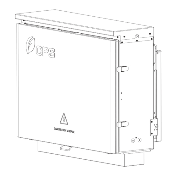
- Page 12 General Introduction Figure 2-3 Product Appearance Component Note Buckle latch For locking and unlocking the front shade cover Handle For opening and closing front shade cover Front cover For sealing, providing protection for the breaker box Mounting holes on the top of the breaker Mounting hole box for lifting handles and eyebolts External Grounding...
- Page 13 General Introduction Features of the Breaker Box Powerful protection performance Provides two 800 Vac 400 A rated circuit breakers. Circuit breaker interrupting capacity of 50 kA at 800 Vac. Constant thermal protection and magnetic protection (Ii=10In). The rated current and de-rating ambient temperature of the circuit breakers is shown in the following table: Rated current...
- Page 14 Figure 2-5 Naming convention of the model IMPORTANT! • If there is any problem or malfunction of the device during operation, you can contact CPS Customer Service and provide the device serial number. Please keep the nameplate complete and intact. 14 / 47...
- Page 15 General Introduction Circuit Structure Design The electrical schematic diagram of the breaker box is shown in Figure 2-6. The AC output power from the PV inverters is connected to the input of each individual circuit breaker and then output through combining busbar. OUTPUT 1~3FU 1L1 1L2 1L3...
- Page 16 General Introduction Storage Requirements • Close the front cover tightly with buckle latches. • Storage space shall be clean, dry, and free of dust or moisture. • The temperature of the storage space shall be kept between -40°F (-40°C) and 158°F (70°C). •...
- Page 17 Mechanical Installation Mechanical Installation Unpacking for Inspection Before unpacking, check whether the packaging box and all safety labels, warning labels, and nameplates on the packaging box and the product are intact. These labels must always be clearly visible and must not be removed or covered. Check the product for any obvious damage and confirm the items in the delivery list are including before performing installation.
- Page 18 Mechanical Installation Installation requirements Flammable and explosive materials inside and around the enclosure are strictly prohibited. Good ventilation around the equipment shall be kept. The operating temperature range is -22°F to 140°F (-30°C to 60°C). If the environment temperature is more than 131°F (55°C), the breaker box must not be installed in direct sunlight.
- Page 19 Mechanical Installation 3.2.1 Installation Modes Requirements Figure 3-2 Installation modes requirements The breaker box must be installed according to the following the modes: If the location permits, install the breaker box vertically. If the breaker box cannot be mounted vertically, it may be tilted backward by lower than 15 degrees from vertical direction.
- Page 20 Mechanical Installation Installation Procedures WARNING! All the installation and wiring connections should be performed only by qualified technical personnel. CAUTION! Heavy device, move it carefully to prevent it from falling! Install the breaker box on rack as shown below: Mark the positions of mounting holes on the installation structure (shelter, steel rack, etc.) according to the size of the mounting brackets.
- Page 21 Mechanical Installation Drill holes with a Ф12mm drill at the marked position, and then install the mounting bracket ② on installation structure ① with M12x40 screw ③, M12 flat washer ④, M12 spring washer ⑤, and M12 nut ⑥. Tool: No.17 hex. socket wrench;...
- Page 22 Mechanical Installation Hang hooks of breaker box into mounting holes of the mounting bracket by either: Manual Mounting: install four handles into the mounting holes as indicated in blue in the figure below. Four people are needed to properly hold the handles and then lift the breaker box. Figure 3-6 Hanging Breaker Box by handles Machine Mounting: tighten two eyebolts to the mounting holes as indicated in blue in the figure below.
- Page 23 Mechanical Installation Use two M6x16 screws to fasten the sides of breaker box on mounting bracket. Tools: No. 10 hexagon socket wrench, torque: 53.1 in-lb (6 N·m). Figure 3-8 Fasten the bracket WARNING! The owner or its structural engineer shall be responsible for choosing an appropriate mounting structure and making proper performance evaluations to make sure the mounting structure is strong and sturdy enough to bear the weight of the breaker box and its material is suitable...
- Page 24 Operation and Maintenance Electrical Connection WARNING! This product works with high AC voltage. Check all the input and output cables or terminals to ensure there is no voltage before accessing electrical connections to avoid electric shock. CAUTION! Connect the cables according to the phase labels on the device to avoid short circuit hazards.
- Page 25 Operation and Maintenance Lift the handle outwards, the front cover will automatically open. Figure 4-2 Lift the handle NOTICE! Keep a safe distance to the front cover when opening it to avoid collisions. Unscrew the 6 screws on the protection cover, remove the protection cover by pulling two handles.
- Page 26 Operation and Maintenance 4.1.2 Create Conduit Entry Holes There is a removable baseplate at the bottom of the enclosure for creating the conduit entry holes. Perform according to the following steps: Remove the baseplate from the enclosure by loosening twelve M5 screws with a No 2.
- Page 27 Operation and Maintenance Figure 4-6 Reinstall the bottom plate Install the conduit and fittings to the bottom plate. Figure 4-7 Install conduit and fittings IMPORTANT! All conduit entries must use watertight fittings. 27 / 47...
- Page 28 Operation and Maintenance Wiring Terminals and Cable Specification This wiring terminal figure shows that DBA02-US-800 has 2 breakers. The following example will demonstrate the operation. 4.2.1 Cable Specification Figure 4-8 Wiring terminals Name Cable Specification Input terminal (Copper 4/0AWG~800kcmil Cu/AL, 90°C busbar) rated.
- Page 29 Operation and Maintenance 4.2.2 Cable Specification and Wiring Torque User copper or aluminum wire. Field wiring conductor of branch circuit: the temperature rating of 90°C for field installed conductors. Copper Bar Cable Wire size Torque Input wire Output wire quantity quantity 4/0 AWG 250 in-lb / 28.2 N·m...
- Page 30 Operation and Maintenance Wiring 4.3.1 Grounding 4.3.2.1 External Grounding The external grounding lug dimension is shown in the following figure. Figure 4-9 External Grounding Lug Dimension Crimp PE cable and connect PE cable to external PE point located at the side of the breaker box.
- Page 31 Operation and Maintenance 4.3.2.2 Internal Grounding The internal grounding terminal is located at the lower right side inside the breaker box, as shown in the following figure. Figure 4-11 Internal grounding terminal Perform internal grounding according to the following steps: Strip approximately 0.6 in (15 mm) of insulation from the end of the cable, exposing the conductor underneath.
- Page 32 Operation and Maintenance Insert the crimped PE cable into the hole of the hole, tighten the compression bolt to secure the PE cable according to the torque value provided in Table 4-3. Figure 4-14 Tighten PE cable 32 / 47...
- Page 33 Operation and Maintenance 4.3.2 Input Cable and Output Cable Connection The specification requirements for input busbar, output busbar on the terminal and the lug holes are shown in the figure below. Figure 4-15 Input busbar specifications Figure 4-16 Output busbar specifications 33 / 47...
- Page 34 Operation and Maintenance Follow the steps below to connect input and output cable: Insert exposed core wires of input and output cables ① into crimp area of compression lugs ③ and wrap with heat shrink tubing or insulation tape ②, and crimp them using hydraulic plier.
- Page 35 Operation and Maintenance For output cable: remove the pre-installed M12 nuts, M12 flat washers and M12 screws from output terminals. Connect the crimped output cable lugs to the output terminals, and then fasten them. Figure 4-19 Connect output cable to output terminal CAUTION! Connect the cables according to the phase labels on the device to avoid short circuit hazards.
- Page 36 Operation and Maintenance After finishing all the cable connections, apply watertight sealants around the internal and external conduit fittings. Figure 4-20 Apply watertight sealants IMPORTANT! The wire stripping position should be ≥1.97 in (50 mm) higher than the bottom of wire box. The cable outside the seal ring should be vertical for at least 11.8 in (300 mm).
- Page 37 Operation and Maintenance Restore the Protection Cover and Close the Front Cover After completing the wiring, restore the protection cover and front cover to their original positions following the steps below: 4.4.1 Restore the Protection Cover Align the two locating holes of the protection cover with the locating pins, and hang it on the locating pins.
- Page 38 Operation and Maintenance 4.4.2 Close the Front Cover Push and hold the protective sleeve of support rod ① to unlock it, then pull handle ② on the front cover to close it. Figure 4-23 Close the front cover NOTICE! Keep a safe distance between yourself and the front cover when opening it to avoid collisions.
- Page 39 Operation and Maintenance Operation and Maintenance CAUTION! The breaker box must not be put into service until all installation and inspection procedures are completed. Close and Open Breaker 5.1.1 Check before Closing Breaker WARNING! Make sure to disconnect and de-energize all circuits to the breaker box prior to commencing any product maintenance.
- Page 40 Operation and Maintenance 5.1.2 Close Breaker Open front cover according to Section 4.1.1. Use the extension handle to sequentially close and energize the breaker to position “I” as shown in the figure below. Remove the extension handle after closing the breaker. Figure 5-1 Close the breaker using extension handle WARNING! Before operating the extended handle, ensure all connections are securely...
- Page 41 No operation by a non-specialist. • Replace the components only with the original parts of the same model if necessary, or you can contact CPS Customer Service for assistance. • Parallel Energy Source! Disconnect all sources supply (utility and Inverter) before change fuse.
- Page 42 Operation and Maintenance Follow the steps below to replace the fuse and SPD: Open front shade cover and protection according to Section 4.1.1. Rotate the isolating switch to “OFF” position. Figure 5-2 Turn off the isolating switch Use a multi-meter to measure the voltage at the inlet end of fuse to confirm there is no voltage.
- Page 43 Operation and Maintenance SPD Replacement: If the SPD indicator ② changes from green to red, it indicates that the SPD is damaged and should be replaced. Remove the SPD fuse ① from the top, press the tab ③ on the back of SPD to slide it off the guide rail, replace the SPD with the same model, replace the SPD fuse according to the specification in Section 6.1, and place the replaced SPD back onto the guide rail.
- Page 44 Technical Data Technical Data Breaker Box Technical Data Product model DBA02-US-800 Compatible inverter CPS SCH350KTL-DO/US-800 Input parameters Number of input circuits OCPD type Circuit breakers OCPD rating 400 A Rated voltage 800 Vac Rated input current 400 A per circuit breaker...
- Page 45 Operation and Maintenance Impact of Cable Length on Breaker Box Performance When selecting the CPS breaker box, systems with a capacity of up to 3.3 MW can be used directly. For systems exceeding 3.3 MW, please choose an appropriate transformer and cable lengths to ensure that the system short-circuit impedance keeps the short-circuit current within 50 kA.
- Page 46 49.957 1.65% 15.24 49.571 1.86% 16.4592 49.849 1.83% 12.192 49.838 1.88% 14.6304 49.661 2.00% 15.8496 49.889 2.03% 17.6784 49.909 2.04% 10.668 49.864 1.62% 12.192 49.957 1.65% Table 6-3 Impact of cable length on short-circuit current for DBA02-US-800 46 / 47...
- Page 47 Contact Information Contact Information For service, Chint Power Systems America will provide technical support. For warranty terms, please refer to the CPS America standard warranty policy in place at time of purchase. CHINT POWER SYSTEMS AMERICA CO., LTD. Address: 1380 Presidential Drive, Richardson, TX 75081...
Need help?
Do you have a question about the DBA02-US-800 and is the answer not in the manual?
Questions and answers