
Summary of Contents for greenfan SFC
- Page 1 SMART FAN CONTROLLER (SFC™) TRAINING MANUAL greenfan inc. ® 353 W. Grove Ave., Orange, CA 92865 Robert Mowris, P.E. 530-448-6249 robert@grenfan.co © Copyright 2004-26 All Rights Reserved...
-
Page 2: Table Of Contents
2.7 Check Transformer ......................5 2.8 Check Fuses ......................... 5 2.9 Other Issues ......................... 5 3. Smart Fan Controller (SFC) ......................7 3.1 Equipment ..........................7 3.2 Pre-Installation Checks ......................7 3.3 Installation for Cooling with Furnace, Hydronic or Electric Heat ........7 3.4 Installation for Heat Pumps .................... -
Page 3: Overview
SWHC059-01 SFC is approved by the California Public Utilities Commission www.caetrm.com/measure/SWHC059/01/ ✓ SFC is more dependable, uses 4 times less standby power (0.3 vs. 1.3W), and saves two times more energy than other fan-off delay controllers ✓ UL listed with 5-year warranty, lasts for life of HVAC equipment or longer ✓... -
Page 4: Check Hvac Fan Relay
SFC™ Training Manual nut connection. If blower continues operating with thermostat fan wire connected to fan relay, then fan relay is faulty or there is a short in thermostat fan “G” wire. Go to 2.2 Check HVAC Fan Relay or 2.3 Check Thermostat Wire Continuity or Install Common-wire Adaptor. -
Page 5: Check Thermostat Wire Continuity Or Install Common-Wire Adaptor
“G” wire is not shorted/open. If there is a short circuit or open circuit on the thermostat fan “G” (or other) wire install a UL-listed common-wire adaptor such as e-wire™ (www.greenfan.co/e-wire). 2.4 Check Minor Cooling or Heating Issues... -
Page 6: Check Capacitors
SFC™ Training Manual Replace pitted or failed contactors. Figure 3. Example of pitted contactors indicating pending failure 2.6 Check Capacitors Start capacitors have a relief plug or disc on top that bulges or leaks if capacitor has overheated. Visually inspect and replace any bulged or leaking capacitors. -
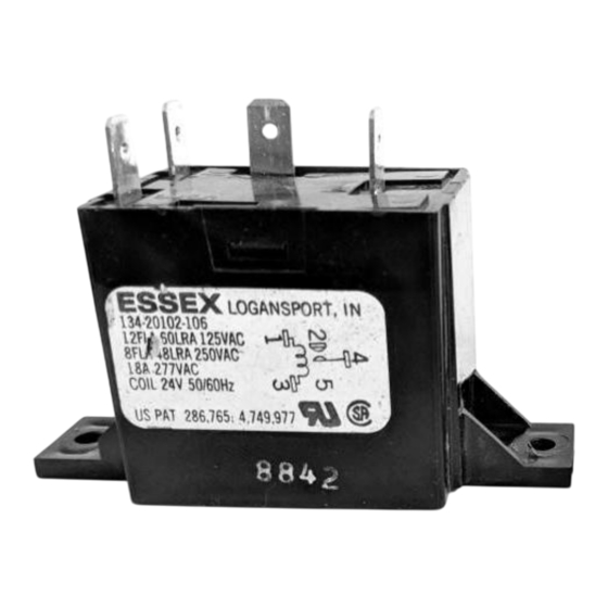
Page 7: Check Transformer
If there is no voltage or low voltage (below 100Vac rms), measure single-phase equipment input voltage or three-phase equipment voltage. If transformer voltage is within 24 ± 4VAC and SFC is not working, then check SFC and thermostat wire connections, fuses, or fan relay. - Page 8 Common and SFC red wire must be connected to 24VAC hot R. SFC black wire to fan G from thermostat and downstream of Ecobee PEK adaptor (if Ecobee). SFC yellow wire to AC Y. SFC white wire to heat W. SFC green wire to fan G terminal on HVAC unit.
-
Page 9: Smart Fan Controller (Sfc)
(usually red) to green (fan), yellow (AC), white (heat), etc. Do not install SFC if HVAC system is not an FAU, HVAC system needs service or repair, or if furnace is on US Consumer Product Safety Commission (CPSC) recall list. See https://www.cpsc.gov/Newsroom/News-Releases/2000/cpsc-warns-about-defective-... -
Page 10: Installation For Heat Pumps
SFC red wire with existing wire and tighten screw (or wire nut). Step 2: Connect SFC white wire to FAU “W” terminal. If unit is a heat pump, leave white wire disconnected. If FAU has separate “Rh” (red heat) do not connect white wire. -
Page 11: Fan Control Check
If SFC does not produce fan delay at end of cooling cycle, ensure SFC yellow wire is connected to FAU Y terminal. If unit is a heat pump do not connect SFC white wire to “W.” Connect white wire as outlined in 3.4 Installation for Heat Pumps. -
Page 12: Troubleshooting Fan Operation Issues
If blower runs continuously with SFC installed, remove thermostat face plate. If blower continues to run with face of thermostat removed, disconnect SFC green and black wires from fan relay connection to temporarily remove SFC fan control. Leave all other wires in place, reconnect thermostat fan wire (usually green) to fan relay terminal, or wire nut connection. -
Page 13: Nonfeasibility
(kBtuh), 13) If HVAC system has a pre-existing fan controller (EFC or Enhanced Time delay) older than 5 years, install a new SFC and enter pre-existing fan controller age from UL or product label (MM/YY). See Figure 6.
Need help?
Do you have a question about the SFC and is the answer not in the manual?
Questions and answers