Advertisement
Quick Links
Advertisement

Summary of Contents for Norco BIS-6360ARA-A10
- Page 1 BIS-6360ARA-A10 Operating Manual...
- Page 2 BIS-6360ARA-A10 Operating Manual Shenzhen NORCO Intelligent Technology Co., Ltd.: 0755-27331166 Beijing Branch: 010-82671166 Shanghai Branch: 021-61212081 Chengdu Branch: 028-85259319 Shenyang Branch: 024-23960846 Xi'an Branch: 029-88338386 Nanjing Branch: 025-58015489 Wuhan Branch: 027-87858983 Tianjin Branch: 022-23727100 For more product information, please visit...
- Page 3 Before ordering products, please ask the distributor to know whether the product performance meets your needs in detail. NORCO is a registered trademark of Shenzhen NORCO Intelligent Technology Co., Ltd. The ownership of other trademarks involved in this manual is owned by the corresponding product manufacturers.
- Page 4 Warm Tips 1. Before using the product, be sure to read the operating manual carefully. 2. For boards that are not ready to be installed, they should be stored in anti-static protection bags. 3. Before taking the board from the packaging bag, put your hands on the grounded metal object for a while to release static electricity from your body and hands.
- Page 5 Contents Contents ................0 Chapter 1 Product Introduction ............4 1.1 Specification ........................4 Chapter 2 Installation Instructions ............7 Instructions for safe use ......................7 2.1 Front view ........................9 2.2 Rear view ........................9 Chapter 3 Hardware Functions ............11 3.1 External interface indicator diagram ................11 3.2 Interface position and dimension drawing ................
- Page 6 4.1.1 HDMI ........................ 33 4.1.2 LVDS .........................33 4.1. 3 USB ........................33 4.1. 4 COM .........................33 4.1.5 CAN ........................33 4.1.6 TF card ......................33 4.1.7 WiFi ........................34 4.1.8 Ethernet ......................34 4.1.9 Sound card ......................34 4.2.0 PCIE interface ....................34 Drivers should be customized according to the actual use of pcie devices by customers.
- Page 7 Packaging List Thank you very much for purchasing NORCO products. After opening the packaging box, please check the accessories according to the packaging list first. If you find that the items are damaged or there is any shortage of accessories, please contact your distributor as soon as possible.
- Page 8 Chapter 1. Product Introduction...
- Page 9 BIS-6360ARA-A10 User's Manual Chapter 1 Product Introduction 1.1 Specification Dimensions ● Size: 188mmx140mmx54.5 mm Processor ● CPU: RK3399, 6-core (dual-core A72 2GHz + quad-core A53 1.5 GHz) System memory ● Onboard memory: ON BOARD memory, support LPDDR4, support 2G/4G Bytes, default 4GB Display ●...
- Page 10 BIS-6360ARA-A10 User's Manual Extracted by 2.00 mm row of needles ● USB: Provide 6 USB interfaces; Among them, 3 USB3.0, 2 USB2.0 are led out through 2.00 mm pin row and 1 OTG interface ● Provide 1-channel PWM ● Provide 1-channel I2C interface Extension ports: ●...
- Page 11 Chapter 2 Installation Instructions...
- Page 12 BIS-6360ARA-A10 User's Manual Chapter 2 Installation Instructions Instructions for safe use Electric current can be used to achieve many useful functions, but it can also cause personal injury and property loss due to improper use. "Safety" is considered as the primary condition in the design and manufacturing process of this product.
- Page 13 BIS-6360ARA-A10 User's Manual ● When you connect or unplug any equipment, make sure that the power cord of all equipment is unplugged before the signal cable is connected ● To avoid the danger of electric shock to human body, turn off the AC power supply or unplug the AC power cord from the power socket every time the system is unplugged or reconfigured.
- Page 14 BIS-6360ARA-A10 User's Manual The data and pictures listed in this article are for illustration only, and are subject to change without prior notice! 2.1 Front view 2.2 Rear view...
- Page 15 BIS-6360ARA-A10 User's Manual Chapter 3 Hardware Functions...
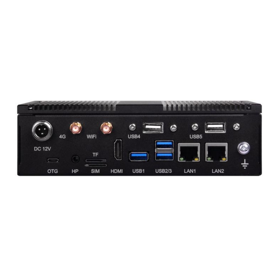
- Page 16 BIS-6360ARA-A10 User's Manual Chapter 3 Hardware Functions 3.1 External interface indicator diagram 3.1. 1: BIS-6360 ARA-A10 Front View WIFI USB4 USB5 DC 12V HDMI TF/SIM LAN2 USB1 USB2/3 LAN1 3.1.2: BIS-6360ARA-A10 rear view COM4 COM6 COM2 USB1/2 HDMI/OUT COM1 COM5 COM7 COM3...
- Page 17 BIS-6360ARA-A10 User's Manual 3.2 Interface position and dimension drawing Note: When handling, please wear electrostatic gloves, because static electricity may damage the components. 3.3 Installation steps Please follow these steps to assemble your computer:...
- Page 18 BIS-6360ARA-A10 User's Manual 1. Adjust all Jumpers on EMB-3537 V1.0 correctly with reference to the user manual. 2. Install other expansion cards. 3. Connect all signal lines, cables, panel control lines and power supplies. The key components of this motherboard are all integrated circuits, and these components are easily damaged due to the influence of static electricity.
- Page 19 BIS-6360ARA-A10 User's Manual 3.4.1 Burning Jumper Down load Default...
- Page 20 BIS-6360ARA-A10 User's Manual 3.4.2 COM 1 Jumper (J1, J2) J1, J2 J1, J2: COM1 AS RS232 PORT COM1 AS RS485 PORT 3-4 5-6 1-3 2-4 3-5 4-6...
- Page 21 BIS-6360ARA-A10 User's Manual 3.4.3 COM2_3 Jumper (J3, J4) J3, J4 J3, J4: COM3 AS RS232 PORT COM3 AS RS485 PORT 3-4 5-6 1-3 2-4 3-5 4-6 3.5 Interface description Please read this manual carefully before connecting external connectors to avoid damage to...
- Page 22 BIS-6360ARA-A10 User's Manual 3.5.1 USB interface (USB3_1, USB3_23, USB2_12, OTG) Provides 6 USB interfaces; 3 USB3.0 interfaces with exposed panels, 2 USB2.0 interfaces through 2.00mm pin headers, and 1 OTG interface USB2_12 USB3_1 USB3_23 USB2_12: Signal name Signal name HUB_1-R...
- Page 23 BIS-6360ARA-A10 User's Manual 3.5.2 Ethernet Interface (LAN) Two RJ45 network interfaces are provided, yellow indicates data transmission status and green indicates network connection status. LAN2 LAN1 RJ45 LAN LED status description: LILED (green) state Function ACTLED (yellow) status Function 100/1000 m link...
- Page 24 BIS-6360ARA-A10 User's Manual 3.5.3 Headphone Interface (HP)
- Page 25 BIS-6360ARA-A10 User's Manual 3.5.4 Power amplifier interface (AUDIO) AUDIO AUIO: Signal name Signal name VCC3 OUTPL OUTNL MIC+ OUTNR MIC- OUTPR Note: Connect the microphone. If it is a single-ended input microphone, the positive pole is connected to PIN5 (MIC +) and the negative pole is connected to PIN3 (MIC-). If it is a differential input...
- Page 26 BIS-6360ARA-A10 User's Manual 3.5.5 Display interface (HDMI) Provide 1 HDMI HD display interface with 4K @ 60Hz resolution HDMI HDMI: Signal name Signal name D2 + D2 Shield D1 + D1 Shield D0 + D0 Shield CK + CK Shield...
- Page 27 BIS-6360ARA-A10 User's Manual + 5V HP DET 3.5.6 Interface (TF) Provide a TF card interface. 3.5.7 Power interface (PWR) A power outlet and a 1x2 pin 2.54 mm small white seat are provided on the board.
- Page 28 BIS-6360ARA-A10 User's Manual PWR: Signal name + 12V 3.5.8 WiFi interface (ANT1) The motherboard provides 1 WIFI interface.
- Page 29 BIS-6360ARA-A10 User's Manual ANT1 3.5.9 MINI PCIe interface and SIM card slot Users can expand MINI PCIe devices according to their own needs...
- Page 30 BIS-6360ARA-A10 User's Manual MINI_PCIE 3.5.10 PCIe interface The motherboard provides a PCIe interface, and users can expand PCIe devices according to their own needs.
- Page 31 BIS-6360ARA-A10 User's Manual PCIE 3.5.11 Serial interfaces (COM1, COM2_3, COM4_7) 6 serial ports are provided, of which COM1/3-> RS232/RS485/TTL is led out through 2*5PIN 2.00 mm pin arrangement; COM4-7-> RS232/TTL. Extracted by 2*20PIN 2.00 mm row of needles...
- Page 32 BIS-6360ARA-A10 User's Manual COM4_7 COM2_3 COM1 COM1: Signal name Signal name DATA- DATA +/RXD COM2_3: Where DB_RXD and DB_TXD are debugging serial ports Signal name Signal name DATA- DB_RXD DATA +/RXD DB_TXD...
- Page 33 BIS-6360ARA-A10 User's Manual COM4_7: Signal name Signal name...
- Page 34 BIS-6360ARA-A10 User's Manual 3.5.12 Programmable input output port (GPIO) GPIO GPIO: Signal name Signal name 3.3V SPI5_RX_33 I2C4_SCL SPI5_TX_33 I2C4_SDA SPI5_CLK_33 GPIO SPI5_CS_33 I2S_SDI I2S_SCLK I2S_SDO I2S_LRCK_RX I2S_CLK I2S_LRCK_TX...
- Page 35 BIS-6360ARA-A10 User's Manual MIPI_TX0_D0N MIPI_TX0_D0P MIPI_TX0_D1N MIPI_TX0_D1P MIPI_TX0_CLKN MIPI_TX0_CLKP MIPI_TX0_D2N MIPI_TX0_D2P MIPI_TX0_D3N MIPI_TX0_D3P 3.5.13 EDP FPC socket (J6) needs to be re-made as an expansion board Seposon model: Trimer Electronic FPV-12W0518-Ruzp 18PIN 0.5 mm Pitch H=2. 0mm Drawer Down FPC Connector...
- Page 36 BIS-6360ARA-A10 User's Manual PWR: Signal name EDP_AUXN EDP_AUXP EDP_TX1N EDP_TX1P EDP_TX0N EDP_TX0P I2C2_SDA I2C2_SCL GPIO2_B1 GPIO2_B0 3.3V 3.3V...
- Page 37 Chapter 4 Software Functions...
- Page 38 BIS-6360ARA-A10 User's Manual Chapter 4 Software Functions 4.1 Android 9 system 4.1.1 HDMI Support HDMI output Instructions: Use HDMI cable to connect the motherboard with the monitor, and you can see the Android interface after starting up. 4.1.2 LVDS Not supported 4.1.
- Page 39 BIS-6360ARA-A10 User's Manual 4.1.7 WiFi Support, see Android interface for specific operating Instructions: Open Settings-> Wireless and Network-> Wi-Fi under the system, turn on Wi-Fi, and you can view the SSID of the searched wireless router on the right, select one of them to connect, and enter the password if the router has a password 4.1.8 Ethernet...
- Page 40 Appendix...
- Page 41 BIS-6360ARA-A10 User's Manual Appendix Appendix I: Glossary of terms ACPI Advanced Configuration and Power Interface. The ACPI specification allows the operating system to control most of the power of computers and their additional devices. Windows 98/98 SE, Windows 2000, and Windows ME all support this specification, giving users the flexibility to manage system power.
- Page 42 BIS-6360ARA-A10 User's Manual A general-purpose serial communication interface, generally using a standard DB 9 male interface connection. DIMM Dual in-line memory modules. It is a small circuit board with a memory chipset. Provide 64bit memory bus width. DRAM Dynamic random access memory. It is a general-purpose memory type for ordinary computers.
- Page 43 BIS-6360ARA-A10 User's Manual operating on the system, including checking RAM, keyboard, hard disk drive, etc. to see if they are connected correctly and working properly. PS/2 An interface specification developed by IBM for keyboard and mouse connection. PS/2 is a 6PIN DIN interface that can also be used to connect other devices, such as modems.
- Page 44 This device complies with part 15 of the FCC Rules. Operation is subject to the following two conditions: (1) this device may not cause harmful interference, and (2) This device must accept any interference received, including interference that may cause undesired operation.
Need help?
Do you have a question about the BIS-6360ARA-A10 and is the answer not in the manual?
Questions and answers