
Subscribe to Our Youtube Channel
Summary of Contents for Pro Vision DR-200
- Page 1 DR-200 V2 Drive Recorder System GUIDE provisionusa.com Rev. D - 6/26/2023 ©2023 PRO-VISION Solutions, LLC.
- Page 2 Viewing Videos Transferred with Software ........................33 File Structure and File Naming ............................33 Troubleshooting ..................................34 DR-200 Unit Status Lights ..............................34 External Event Marker Button Status Light ........................34 DR-200 Unit Troubleshooting ............................35 Web/Viewing Troubleshooting ............................37 Wi-Fi Troubleshooting ...............................
- Page 3 DR-200 V2 System Guide Rev. D - 6/26/2023 IMPORTANT NOTICES PRO-VISION tries to ensure that the information provided in this document is as comprehensive as possible at the time of publication. However, because of PRO-VISION’s drive to provide the best products through continual improvement, PRO- VISION reserves the right to update the information in this document at any time without prior notice.
- Page 4 Connect and install power cable and trigger wires (if applicable). Mount the DR-200 Drive Recorder to the windshield and install the SD card. (Turn on the ignition and connect to the unit via Wi-Fi to verify camera views if needed before attaching adhesive to glass.) Route third camera cable(s) to camera mounting location (if applicable).
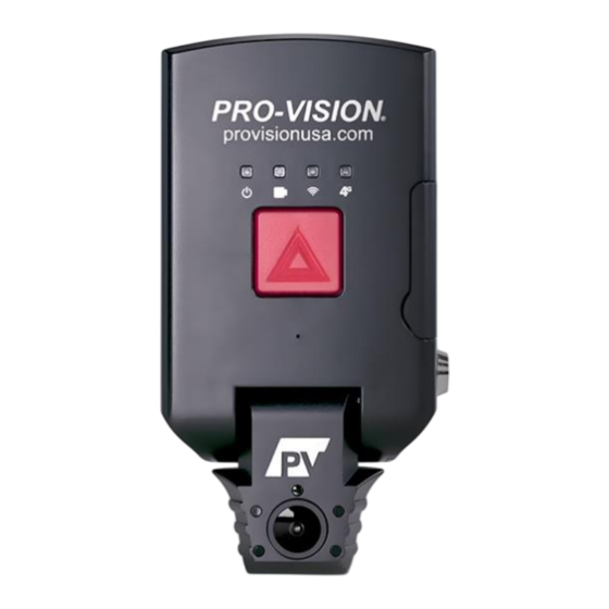
- Page 5 Drive Recorder Unit The DR-200 Drive Recorder unit is a self-contained recording system. It combines the functions of a traditional mobile DVR Unit, Forward Facing Camera, Interior Camera, GPS Antenna, and Event Marker Button into a single housing.
- Page 6 SD Card The DR-200 drive recorder kit includes one SD card, the size of the card varies by the kit option bought, the minimum size is (1) 32 GB SDHC card (Part # PD-1716). The SD card is the storage device for the unit and stores all recorded video and operation logs.
- Page 7 DR-200 V2 System Guide Rev. D - 6/26/2023 Drive Recorder Installation Installation Process There are two main components of the physical installation: 1. Installing and connecting the power cable 2. Mounting the unit to the windshield. Selecting an installation location for the unit: Power the unit on and connect to its Wi-Fi.
- Page 8 DR-200 V2 System Guide Rev. D - 6/26/2023 Installing Power Cable The power cable supplies power and controls when the unit is on or off. Ensure that the green and red fuse holders are installed in line with the RED "12V DC POWER" wire and the GREEN "12V DC IGNITION POWER" wires, respectively.
- Page 9 System Guide Rev. D - 6/26/2023 Removing Mount from Unit The DR-200 unit is shipped with the standard adhesive mount attached to the camera and must be removed before installation. 1. Unlock the SD Door lock. 2. Open the SD card access door by gently pulling on the tab on the door near the lock.
- Page 10 Attaching the mount to the glass: Hold the DR-200 unit in place when selecting the final mounting location. Holding the unit in place and marking the intended location with tape along the side and top is useful in unit placement to ensure the device is level.
- Page 11 DR-200 V2 System Guide Rev. D - 6/26/2023 Attaching Camera to Mount 1. Align the notches on the back of the device with the pins on the bracket. 2. Slide the device onto the bracket until you hear a click.
- Page 12 System Guide Rev. D - 6/26/2023 Aiming the Cameras The DR-200 cameras are built into the lower portion of the drive recorder. The unit is hinged to allow adjustment for the slope of the windshield. Adjusting the bottom camera portion: The DR-200 camera comes with position lock screws tightened.
- Page 13 External Camera and Cable Routing The DR-200 unit has two built-in cameras and supports a third externally mounted camera that can be connected to the main unit; this allows up to three (3) cameras to simultaneously record video. The third camera can be either a DVR-824 HD Stop-Arm Camera or any analog camera connected through a PX-1210 Analog Camera Adapter.
- Page 14 • Solid power LED when the device is powered on. • Flashing GREEN camera LED when device is communicating with DR-200 unit. • Solid GREEN camera LED when recording. Cable Extension Configuration: The extensions must be configured as described previously: •...
- Page 15 Cable Routing: Once the locations of DR-200 unit, cameras, or monitor have been determined, the cable(s) for the components can be routed. Determine the approximate cable routing to the locations of each of the components and remove all panels along the route where the cables will travel.
- Page 16 The Event Marker Button includes 6 m (20 ft.) of cable. This cable needs to be routed starting from the button location to the Event/Trigger cable at the top of the DR-200 unit. The button is usually mounted within reach of the driver using the included adhesive pad.
- Page 17 DR-200 V2 System Guide Rev. D - 6/26/2023 How Trigger Inputs Work: The standard setting for the trigger inputs is such that when a 12 Vdc or 24 Vdc signal is sent to a trigger wire, an alarm recording will be triggered to start, and a corresponding four-character word will display on the screen.
- Page 18 DR-200 V2 System Guide Rev. D - 6/26/2023 Power Protection Feature The unit is equipped with internal supercapacitors that store power for a brief period to prevent system issues and file corruption due to abnormal power supply issues. The supercapacitors also supply power to continue recording for an additional 3 seconds in case of a total power loss in case of a collision.
- Page 19 DR-200 V2 System Guide Rev. D - 6/26/2023 External 4G Antenna Installation If the optional 4G version was bought, one (1) external 4G antenna is included with the system. It should be connected to the 4G connection port on the side of the unit. The antenna must be installed for the 4G to function.
- Page 20 The DR-200 Drive Recorder unit can only be accessed wirelessly using a laptop, tablet, or smartphone device. 1. Ensure that the DR-200 unit is powered on (solid green power LED) and that the Wi-Fi is on (flashing slowly yellow Wi-Fi LED). The yellow LED will flash slowly until a device is connected to the local SSID (network name) that the DR-200 is broadcasting.
- Page 21 DR-200 V2 System Guide Rev. D - 6/26/2023 Viewing and Aiming Cameras From the home page of the web interface use the Live View button to view the camera views in real time. Once on the Live View page, the camera images may be seen. These are not the same quality as the recorded video, as they are lower resolution images that refresh 1 time per second and display the field of vision of connected cameras.
- Page 22 DR-200 V2 System Guide Rev. D - 6/26/2023 System Info To view system information, click the “Info” option from the left navigation menu. Also, the information is displayed on the system info box on the right side of the page (Device, Unit ID, S/N, Firmware Version, Power Source, Ignition Status, SSID Name with indicator bar of signal strength, 4G LTE with indicator bar of signal strength, Storage Type - storage status with indicator bar of percentage used, Front Camera, Inside Camera, CAM3 - if connected).
- Page 23 Setup Process (Repeat the steps below for each vehicle/unit) 1. Insert the prepared SD card into the SD card slot on the unit (under the side door of the DR-200 unit). If there is an SD card already loaded, remove it temporarily and reinsert after the setup process using the prepared SD card is completed.
- Page 24 DR-200 V2 System Guide Rev. D - 6/26/2023 Settings When the unit is first installed, there are a few settings that should be configured. In the left side menu, choose the Basic option to begin setting these values. Basic The basic settings are the minimum settings that should be set/verified on each unit.
- Page 25 DR-200 V2 System Guide Rev. D - 6/26/2023 Camera This page allows custom titles to be assigned for the camera views and allows a warning beep to indicate a camera signal loss. The cameras can be configured all at once to the same values by selecting “ALL”...
- Page 26 Audible Alarm: Enable an audible tone to alert the operator that an Event Marker has been activated. Overspeed: This is the GPS speed at which, if enabled, the DR-200 will trigger for overspeed. The OSD will display the value in the OSD box, the cameras will record in alarm mode (if set), and the audible alarm will sound (if enabled).
- Page 27 G-Force The DR-200 V2 unit has a built-in G-Force sensor that can be used as a trigger to activate alarm recording. The sensor must be calibrated after the system is installed. To calibrate, ensure the DR-200 V2 unit is mounted and the vehicle is parked on a level surface and then follow the onscreen prompts on the G-force page to complete the calibration.
- Page 28 DR-200 V2 System Guide Rev. D - 6/26/2023 Wi-Fi The Wi-Fi connection is important to the device as it is used for camera aiming, configuration, and file transfer. Wi-Fi Info: This section shows the status of the current connection. By default, the unit is in “AP Mode”...
- Page 29 Select the IP Mode of the network to be connected, if unsure, leave it at DHCP as this is recommended. e. Press “APPLY” at the bottom of the page. The Wi-Fi on the DR-200 unit will turn off, then turn back on using Wi-Fi Client Mode and the SSID/Password entered.
- Page 30 DR-200 V2 System Guide Rev. D - 6/26/2023 4G LTE If the device was bought as a 4G device (DR-200-4G), this page is used to configure the settings. 4G LTE Info: Information about Connection Status, Modem (Normal or Not Found), SIM, Carrier, SIM Number, IMEI, Signal Strength, and Network is listed in this section.
- Page 31 DR-200 V2 System Guide Rev. D - 6/26/2023 User The “User” page is only accessible to an “Admin” user account. This page allows the customization, addition, and changing of passwords and permissions for user accounts. There are four user accounts created by default with various permission levels.
- Page 32 DR-200 V2 System Guide Rev. D - 6/26/2023 USER OPERATION Event Marker Button The length of the pre-event and post-event recording and Event Button functionality can be changed on the Triggers page. Depending on system settings, pressing the Event Marker/Panic button will either: 1.
- Page 33 DR-200 V2 System Guide Rev. D - 6/26/2023 Drive Recorder Status Lights Power Status Indicator LED (GREEN Color) Unit is OFF with no ignition signal. ON SOLID GREEN Unit is ON or powering up with Ignition Signal ON. FLASHING GREEN Unit is ON with Ignition Signal OFF;...
- Page 34 Rev. D - 6/26/2023 VIDEO PLAYBACK There are multiple methods of playing back video from the DR-200 Drive Recorder unit: 1. Directly from the DR-200 unit through a web browser. 2. Removing the SD Card and connecting it to a computer.
- Page 35 Rev. D - 6/26/2023 Viewing Video from the SD Card The DR-200 unit stores video on an SD Card. It can be removed and connected to a computer for review. 1. Use a key to unlock the SD card on the side of the DR-200 unit.
- Page 36 ON SOLID GREEN DR-200 Unit is ON and recording from at least one camera LED) FLASHING RED DR-200 Unit is ON but not recording due to problem, or button cable is damaged ©2023 PRO-VISION Solutions, LLC. Page 34 of 42...
- Page 37 DR-200 unit has no ignition signal. proper connection and check the fuse when the vehicle key is ON. DR-200 units are shipped with a high (12 Vdc - 24 Vdc) ignition level DR-200 unit has lights on but will Ignition signal is set improperly.
- Page 38 Test to ensure it is a camera problem by exchanging that camera A camera is not working properly or is with a known, good camera or using another DR-200 unit. Check the damaged. Live View page to ensure that an image is being received from the camera.
- Page 39 There was an error initializing the live Ensure the DR-200 is upgraded to the latest version of firmware. Go video display. If the recording LED is https://firmware.provisionusa.com to download the latest firmware on solid green or flashing green, the or connect the DR-200 to the internet via the building's Wi-Fi.
- Page 40 Wi-Fi signal goes in and out. The Wi-Fi is rebooting. changes to take effect. If the DR-200 unit is rebooting, each time it will shut down the Wi-Fi The DR-200 unit is rebooting. during the reboot. The DVR is not connected to a...
- Page 41 LED is flashing green before removing the SD card. If the status light recording. is solid green, press the STOP button on the front of the DR-200 and wait until the light begins flashing before removing the disk. Ensure that all disk folders and playback software are closed before removing the disk from the computer.
- Page 42 DR-200 unit cable. unit interface cable. EVT/Triggers cable on DR-200 unit is Check the cable to ensure that it is fully connected to DR-200 unit. not fully connected or is damaged. External Event Marker Button light is not working.
- Page 43 UPDATES Pro-Vision periodically releases new firmware for this device. • To view the latest firmware available, visit https://firmware.provisionusa.com/Products/Page/DR-200%20v2. • To determine if an update is needed, check the current firmware version on your device, it can be viewed through the web user interface on the right side, then compare this version against the latest available.
- Page 44 Rev. D - 6/26/2023 COMPLIANCE The PRO-VISION model DR-200 Drive Recorder is a radio transmitter and receiver. It is designed and manufactured not to exceed the emission limits for exposure to radio frequency (RF) energy set by the Federal Communications Commission (FCC) of the U.S.
Need help?
Do you have a question about the DR-200 and is the answer not in the manual?
Questions and answers