
Related Manuals for NAFFCO NFY-JD01-M1

Summary of Contents for NAFFCO NFY-JD01-M1
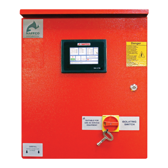
- Page 2 JOCKEY CONTROLLER INSTALLATION OPERATION AND MAINTENANCE INSTRUCTIONS 1. General Jockey pump controllers, are installed in the same system as Main fire pump Controllers. Their primary function is to maintain normal water pressure which may fluctuate slightly due to small leaks in the system and therefore prevent short cycling of the main fire pump.
- Page 3 JOCKEY CONTROLLER INSTALLATION OPERATION AND MAINTENANCE INSTRUCTIONS • Carefully inspect and clean equipment • Inspect and re-tighten all electrical connections • Perform visual inspection of the power contacts of the main contractor, circuit breaker and disconnect switch. • Perform a no load test and check all continuities 3.
- Page 4 JOCKEY CONTROLLER INSTALLATION OPERATION AND MAINTENANCE INSTRUCTIONS 4.1.1 STOPPING OPERATION Auto-STOP : Controller start the motor automatically when the ACTUAL pressure reach START PRESSURE value and stop the motor automatically when minimum run time (MRT) get over and pressure reach STOP pressure value . Manual-STOP : User can press OFF button at any moment to stop the motor (MRT is not applicable on manual stop).
- Page 5 JOCKEY CONTROLLER INSTALLATION OPERATION AND MAINTENANCE INSTRUCTIONS 5. TOUCH PANEL HARDWARE AND SOFTWARE STRUCTURE CONNECTIONS DO-1 DO-2 DO-3 DO-4 YH-J-T1 Pressure Sensor AC Power Supply Subject to change without prior notice 5 of 25 Ref. No. NF-JP-M1-IOM/2022/V.01...
- Page 6 JOCKEY CONTROLLER INSTALLATION OPERATION AND MAINTENANCE INSTRUCTIONS User can enter settings page by Pressing SETTINGS button on front panel Enter Password BACK **** Settings Summary Display Backlight Voltage Settings Pressure Settings Timers Digital Inputs Digital Outputs Change Password Product Information Subject to change without prior notice 6 of 25 Ref.
- Page 7 JOCKEY CONTROLLER INSTALLATION OPERATION AND MAINTENANCE INSTRUCTIONS DISPLAY SETTINGS Display Setting BACK Backlight Brightness Backlight saver Mode Backlight OFF time DISPLAY BRIGHTNESS Display Setting / Display Backlight BACK Selection: [ 100 ] % Range: (10 – 100) Subject to change without prior notice 7 of 25 Ref.
- Page 8 JOCKEY CONTROLLER INSTALLATION OPERATION AND MAINTENANCE INSTRUCTIONS DISPLAY BACKLIGHT SAVER MODE Display Setting / Backlight saver mode BACK Select : Enable Disable Enable Display backlight ON time duration on save mode : Display Setting / Backlight OFF Time BACK Selection: [ 60 ] Sec Range: (10 –...
- Page 9 JOCKEY CONTROLLER INSTALLATION OPERATION AND MAINTENANCE INSTRUCTIONS VOLTAGE SETTINGS Voltage Settings BACK Voltage System Voltage Value Over Voltage Under Voltage Voltage Settings / Voltage System BACK Selection: [ 3 phase ] Single Phase 3 Phase 3 Phase + N Subject to change without prior notice 9 of 25 Ref.
- Page 10 JOCKEY CONTROLLER INSTALLATION OPERATION AND MAINTENANCE INSTRUCTIONS RATED VOLTAGE Voltage Settings / Voltage Value BACK Selection: [ 380 ] VAC Range: (90 - 600 ) OVER VOLTAGE ALARM VALUE Voltage Settings / Over Voltage BACK Selection: [ 420 ] VAC Range: (90 - 700 ) UNDER VOLTAGE ALARM VALUE Voltage Settings / Under Voltage...
- Page 11 JOCKEY CONTROLLER INSTALLATION OPERATION AND MAINTENANCE INSTRUCTIONS PRESSURE SETTING Pressure Settings BACK Pressure Unit Rated Pressure Start Pressure Stop Pressure Pressure Sensor Low Pressure Alarm High Pressure Alarm PRESSURE UNIT SELECTION FOR DISPLAY VALUE The unit change will come into effect in all areas of pressure value settings and display in controller Pressure Settings/Pressure Unit BACK Selection: [ BAR]...
- Page 12 JOCKEY CONTROLLER INSTALLATION OPERATION AND MAINTENANCE INSTRUCTIONS RATED PRESSURE Pressure Settings / Rated Pressure BACK Selection: [ 9.5 ] BAR Range: (0.0 - 50 ) START PRESSURE The controller start the motor when pressure reach the start pressure value and this value will display on front panel Pressure Settings / Start Pressure BACK Selection: [ 10.5 ] BAR...
- Page 13 JOCKEY CONTROLLER INSTALLATION OPERATION AND MAINTENANCE INSTRUCTIONS STOP PRESSURE The controller stop the motor when pressure reach the stop pressure value and this value will display on front panel ` Pressure Settings / Stop Pressure BACK Selection: [ 10.5 ] BAR Range: (0 - 50 ) SENSOR SELECTION Pressure Settings/Pressure Sensor...
- Page 14 JOCKEY CONTROLLER INSTALLATION OPERATION AND MAINTENANCE INSTRUCTIONS LOW PRESSURE ALARM VALUE SETTING Pressure Settings / Low Pressure Alarm BACK Selection: [ 7 ] BAR Range: (0 - 50 ) HIGH PRESSURE ALARM VALUE SETTING Pressure Settings / High Pressure Alarm BACK Selection: [ 13 ] BAR Range: (0 - 50 )
- Page 15 JOCKEY CONTROLLER INSTALLATION OPERATION AND MAINTENANCE INSTRUCTIONS Timers BACK Sequential start timer (SST)) Minimum Run Timer (MRT) Minimum Restart Timer (PRT ) Star-Delta Timer (SDT) Fail to Start Timer SEQUENTIAL START TIMER (SST) SST is the motor start delay time from when the system pressure value reaches the START pressure value. Minimum Restart time applicable in it .
- Page 16 JOCKEY CONTROLLER INSTALLATION OPERATION AND MAINTENANCE INSTRUCTIONS MINIMUM RUN TIMER (MRT) MRT is the minimum run time of motor since the RUN signal is active. Motor turns OFF once the MRT count finishes if the actual pressure value reaches STOP pressure within the counting time. But Motor would switch OFF immediately at the moment pressure value reaches the STOP pressure if system achieve the STOP pressure after MRT count finishes.
- Page 17 JOCKEY CONTROLLER INSTALLATION OPERATION AND MAINTENANCE INSTRUCTIONS STAR-DELTA TIMER (SDT) Time delay of star to delta transfer Timers / Star-Delta Timer BACK Selection: [ 5 ] Seconds Range: (0 - 30 ) FAILED TO START TIMER Time delay for activating failed to start alarm after controller sense the failed to start signal . Timers/ Fail to Start Timer BACK Selection: [ 5 ] Seconds...
- Page 18 JOCKEY CONTROLLER INSTALLATION OPERATION AND MAINTENANCE INSTRUCTIONS DIGITAL INPUT PROGRAMING User can assign each DI terminal for available options. Also user can map the same terminal on DO terminals . Digital Inputs BACK DI-1 DI-2 DI-3 DI-4 Digital Inputs / DI-1 BACK Selection: [ Motor Overload ] Interlock...
- Page 19 JOCKEY CONTROLLER INSTALLATION OPERATION AND MAINTENANCE INSTRUCTIONS DIGITAL OUTPUT PROGRAMING User can assign each DO terminal for available options. Digital Inputs BACK DO-1 DO-2 DO-3 DO-4 Digital Outputs / DO-1 BACK Selection: [ Main Contactor] Main Contactor Star / Delta Contactor Power ON Pump Run AUTO Mode...
- Page 20 Digital Outputs / DO-1 BACK Selection: [ Main Contactor] Main Contactor JOCKEY CONTROLLER Star / Delta Contactor INSTALLATION OPERATION AND MAINTENANCE INSTRUCTIONS Power ON Pump Run Digital Outputs / DO-1 BACK AUTO Mode Selection: [ Main Contactor] OFF Mode Main Contactor Manual Mode Star / Delta Contactor Low Pressure Alarm...
- Page 21 JOCKEY CONTROLLER INSTALLATION OPERATION AND MAINTENANCE INSTRUCTIONS PASSWORD CHANGE User can change the password through below method. Change Password BACK **** Confirm Password BACK **** Subject to change without prior notice 21 of 25 Ref. No. NF-JP-M1-IOM/2022/V.01...
- Page 22 Project Name :............................Location :............................Commissioned By :............................Date of Commissioning :............................Signature of Commissioning Engineer :............................Ref. No. NF-JP-M1-IOM/2022/V.01...
Need help?
Do you have a question about the NFY-JD01-M1 and is the answer not in the manual?
Questions and answers