
Summary of Contents for GRESSEL R-C2
- Page 1 Assembly and operating manual R-C2 module IO-Link English Article number: XND.00026.005 Doc-Id: 10000048809-G06 Version: A2 www.R-C2.com www.gressel.ch...
- Page 2 Protection against dangerous movements ................12 Protection against electric shock ..................13 Protection against magnetic and electromagnetic fields ............13 Notes on risks ........................14 Technical data ........................... 16 10.1 Basic data ..........................16 www.gressel.ch XND.00026.005 / Version – A2...
- Page 3 R-C2 module mechanical interface ................22 12.2 Structure ..........................23 12.2.1 Design of the R-C2 module and the R-C2 centric clamping vise ........23 12.2.2 Dimensions of the R-C2 module ..................26 12.2.3 Pneumatic diagram of the R-C2 module ............... 27 12.2.4...
- Page 4 Incorrect values from measuring system ..............56 16.1.4 Other malfunctions ....................... 56 16.2 Malfunction to the R-C2 vise ....................56 16.2.1 Mechanical malfunction to the R-C2 vise ..............56 Maintenance ..........................57 17.1 Maintenance interval R-C2 module ..................57 17.2 Maintenance interval R-C2 vise ..................... 58 17.3...
- Page 5 1 Imprint Copyright: This manual is protected by copyright. The author is GRESSEL AG. All rights reserved. In particular, any reproduction, editing, distribution (making available to third parties), translation or other usage – including excerpts – of the manual is prohibited and requires our prior written approval.
- Page 6 Indicates general notes, helpful user tips and operating recommendations that have no impact on the health and safety of the personnel. Emphasizes useful tips and recommendations as well as information pertaining to efficient and failure-free operation. www.gressel.ch XND.00026.005 / Version – A2...
- Page 7 Further information can be found on the GRESSEL AG homepage. * https://www.gressel.ch/anmeldung-r-c2/ *For the download, the following information is required: Name / Company / E-mail address. For technical assistance and support requests, please contact us via e-mail at our R-C2 team: r-c2.support@gressel.ch www.gressel.ch...
- Page 8 3.1 Appropriate use • The product is designed exclusively for coupling/uncoupling, transporting, and operating a GRESSEL R-C2 centric clamping vise or a GRESSEL pallet with R-C2 interface. • The product may only be used within the scope of its technical data (Chapter 10, page •...
- Page 9 In locations with difficult operating conditions, e.g. due to caustic fumes, gases, oils or chemicals • In automated systems requiring special monitoring, e.g. in particularly at-risk areas • In addition, the product may not be used in potentially explosive zones. www.gressel.ch XND.00026.005 / Version – A2...
- Page 10 Observe the valid safety and accident prevention regulations. • Wear close-fitting protective clothing and place a hairnet over long hair when dealing with moving components. • Wearing safety goggles and safety shoes is mandatory. www.gressel.ch XND.00026.005 / Version – A2...
- Page 11 Ensure that no residual energy remains in the system. • If the energy supply is connected, do not move any parts by hand. • Do not reach into the open mechanism or movement area of the product during operation. www.gressel.ch XND.00026.005 / Version – A2...
- Page 12 Before commissioning the machine or automated system, check that the EMERGENCY STOP system is working. Prevent operation of the machine if this protective equipment does not function correctly. www.gressel.ch XND.00026.005 / Version – A2...
- Page 13 A special additional EMC test may be necessary if the system has a high-risk potential. www.gressel.ch XND.00026.005 / Version – A2...
- Page 14 Do not reach into the open mechanism or the movement area of the product. Warning Risk of injury from sharp edges and corners! Sharp edges and corners can cause cuts. Wear suitable protective equipment. www.gressel.ch XND.00026.005 / Version – A2...
- Page 15 Let them cool down before working on the product. Warning Risk of injury due to ejected metal splinters (blow-out function of coupling unit, measuring probe). In general, the R-C2 module is connected to compressed air. Wear protective goggles www.gressel.ch XND.00026.005 / Version – A2...
- Page 16 Heavy duty coupling pins - RCA.000.009.01 (distance from the center of gravity 160 mm) Max. clamping torque 100 Nm Max. clamping force for clamping device R-C2 125 30 kN (depending on speed) Max. traversing speed of the clamping device 1.5 mm/s Operating temperature 15 to 45 °C...
- Page 17 Each clamping device is protected against overload by current limitation (RFID tag information). The R-C2 module can be used to set the clamping force in the permitted ranges in accordance with the situation. The conversion from current to clamping force is carried out using the calculation below.
- Page 18 Speed of 0.5 mm/s, Acceleration of 1 mm/s 2 mm larger than the component pre-positioned (1 mm per jaw), Position travel 5 mm into the component (theoretical target point). X +2 mm X -5 mm www.gressel.ch XND.00026.005 / Version – A2...
- Page 19 Permissible loads The force was measured 20 mm above the R-C2 base body, with smooth jaws and a piezoelectric load cell. einspannung ne lamping trom urrent Conversion formula for fine clamping: Clamping force [kN] = 2.25 x current [A] + 1.8...
- Page 20 For the design of the coupling pins and their fatigue strength, the following values were taken as the reference. 35 kg 11.4.2 Heavy duty coupling pin (RCA.000.009.01) 50 kg 11.5 Permissible acceleration Description Maximum permissible acceleration [g*] Emergency stop Travel acceleration *g = 9.80665 m/s www.gressel.ch XND.00026.005 / Version – A2...
- Page 21 It is also possible to perform a simple pallet handling with the R-C2 module. To achieve this, suitable pallets or the required coupling pins can be ordered from Gressel.
- Page 22 12.1.2 R-C2 module mechanical interface Quick-change system R-C2 The R-C2 module is equipped with a dovetail quick-change system. The R-C2 module can be inserted quickly and accurately into the robot adapter plate and secured with just one M8 fastening screw (20 Nm).
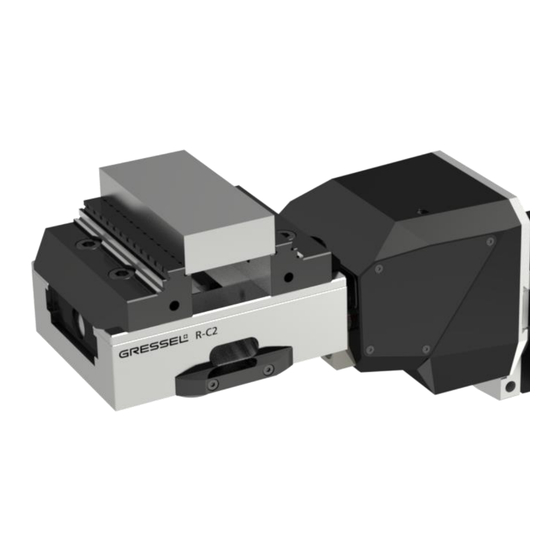
- Page 23 Design and description 12.2 Structure 12.2.1 Design of the R-C2 module and the R-C2 centric clamping vise *Front cover for the inductive sensors is hidden Design of R-C2 module www.gressel.ch XND.00026.005 / Version – A2...
- Page 24 Design and description R-C2 centric clamping vise design The R-C2 module consists of the following main components: Coupling unit (CU) Inductive Sensors RFID antenna Drive piece (Torx nut) Mechanical sensor / measuring probe The coupling unit holds the pins from the counterpart (e.g. the centric clamping vise or pallet). The coupling unit is closed in a depressurized condition, therefore the coupling pins are fixed energy self- sufficient.
- Page 25 Output opening Note The opening width is always related to the slides of the vise. The integrator is responsible for the jaws' correct use. The minimum opening is always 0 mm. www.gressel.ch XND.00026.005 / Version – A2...
- Page 26 The three pneumatic valves ("open coupling unit", "turbo" and "cone blow-out") are supplied internally by the compressed air supply from the R-C2 module. The measuring probe is actuated via the existing sources. The compressed air from the "turbo" extends the measuring probe and the "cone blow-out"...
- Page 27 Design and description 12.2.3 Pneumatic diagram of the R-C2 module Measuring probe 12.2.4 Important dimensions of the centric clamping vise Caution The recommended minimum step height of the reversal jaw is 22 mm. If the minimum jaw height is not reached, a collision between the module housing and the storage rack may occur during the gripping process.
- Page 28 Extra VERO-S covers are available for all 4 vises. For further information regarding the R-C2 vise, please refer to the "Operating manual R-C2 vise". R-C2 clamping devices with length 130 mm are not allowed to use with R-C2 module IO-Link. www.gressel.ch...
- Page 29 IO-Link communication, supply logic – M8 Voltage supply connector Load voltage – 48 V - M12 Ground connection Ensuring grounding between the R-C2 module and the machine/robot Tightening torque screw 1.2 Nm Permissible wire cross-section 0.5 - 1.5 mm / 22 - 16AWG LED –...
- Page 30 Mount the product so that sufficient heat dissipation is guaranteed. A temperature malfunction may occur if the product reaches excessively high temperatures. 13.1.1 Overview of assembly steps 1. Connect R-C2 module with the adapter plate, which is mounted on the handling unit – mechanical connection [chapter 13.2.1 - p.31]...
- Page 31 Assembly and settings 13.2 Connections 13.2.1 Mechanical connection mechanical connection Item Description Information R-C2 module IO-Link Robot adapter plate Robot-specific versions available, please send a request Fastening screw M8x60 - 8.8 Tightening torque 20 Nm 13.2.2 Pneumatic connection Item Description Information Plug coupling - connections ø6 mm hose...
- Page 32 Cable lug for cross section 0.5 -1.5 mm / 22-16 AWG Toothed lock washer R-C2 print cover Ground marking * Tightening torque 1.2 Nm/a cylindrical screw with hexagon socket is supplied A ground connection with a sufficient cross-section must be established between the product and the machine on the customer's premises.
- Page 33 The firmware must be reloaded. • Do not disconnect the product from the power supply. • Unknown malfunctions may occur, resulting in a repair. www.gressel.ch XND.00026.005 / Version – A2...
- Page 34 The potentials are combined again on the electronics; the assignment of the 4 wires is intended to reduce the load for a single wire. IO-Link The IO-Link is connected using an M8 connector, 4-pole, A-coded. PIN allocation of logic voltage connector +24 V C/Q, IO-Link www.gressel.ch XND.00026.005 / Version – A2...
- Page 35 Assembly and settings 13.2.3.2 External protection The power circuit of the R-C2 module must be protected with a fuse by the customer. Note Disconnect from load voltage The power supply unit should be able to deliver 20 A (Note regenerative power supply) The cable length must be <20m (IO-Link specification)
- Page 36 • GRESSEL IO-Link protocol "User", therefor you will get a specific IODD file Note A standard master can be used for communication between the R-C2 product and a PC. As an example: TMG IO-Link Device Tool - Standard Edition www.gressel.ch...
- Page 37 ✓ 4: "Module error" LED does not light up ✓ 5: "Load voltage supply" LED lights up green ✓ 6: "IO-Link connection status" LED lights up orange ✓ 7: "Logic voltage supply" LED lights up green www.gressel.ch XND.00026.005 / Version – A2...
- Page 38 Further information can be found in the software manual. 14.4.1 Project planning of the product in Siemens TIA Note Project planning of the product is described with the project planning software Siemens TIA Portal V16, for example. www.gressel.ch XND.00026.005 / Version – A2...
- Page 39 14.4.2 IODD file 14.4.2.1 Importing IODD files In the example, a Siemens IO-Link master with the part number: 6ES7 547-1JF00-0AB0 is used. The files / file versions mentioned are only examples. Configuring the IO-Link module www.gressel.ch XND.00026.005 / Version – A2...
- Page 40 "Start Device Tool". Please check under “Help / Info” the software version, it must be: S7-PCT version: V3.5 & service pack: SP3 If necessary, update or clarify compatibility with R-C2 Support GRESSEL. www.gressel.ch XND.00026.005 / Version – A2...
- Page 41 Initial operation Import the IODD. Select the IODD file (current data are available on the GRESSEL homepage, R-C2 download) www.gressel.ch XND.00026.005 / Version – A2...
- Page 42 Initial operation Successful import is confirmed. Select product and assign it to the correct port. www.gressel.ch XND.00026.005 / Version – A2...
- Page 43 Initial operation www.gressel.ch XND.00026.005 / Version – A2...
- Page 44 Initial operation Generate a source file for later import in the project: Open external source in project www.gressel.ch XND.00026.005 / Version – A2...
- Page 45 Initial operation Generate module from source www.gressel.ch XND.00026.005 / Version – A2...
- Page 46 Please check the bit order (bit assignment on the correct address). Example from SIEMENS TIA V16: Input data Designations in this table may no longer corresponding to the current status. They are described in English in the software manual. www.gressel.ch XND.00026.005 / Version – A2...
- Page 47 Please check the bit order (bit assignment on the correct address). Example from SIEMENS TIA V16: Output data Designations in this table may no longer corresponding to the current status. They are described in English in the software manual. www.gressel.ch XND.00026.005 / Version – A2...
- Page 48 15 Firmware update 15.1 Update with TMG Master The following describes the procedure of how the firmware of the R-C2 module can be updated using the "IO-Link Device Tool - Standard Edition" from TMG (Technologie Management Gruppe, 76227 Karlsruhe). This TMG Master not included in the scope of delivery and must be ordered separately.
- Page 49 Pressing the "Update Firmware" button opens a dialog box. This lists the current firmware and asks for confirmation of its execution. Pressing the "OK" button will start the process. Do NOT disconnect the IO-Link connection during this process! www.gressel.ch XND.00026.005 / Version – A2...
- Page 50 Depending on the situation, it may be possible to install the correct firmware with a new attempt. In the worst-case scenario, the module will have to be returned to GRESSEL for servicing. www.gressel.ch XND.00026.005 / Version – A2...
- Page 51 Otherwise, an update will not be possible. For a successful execution of the firmware update, the Siemens S7 "Device Tool / Port Configuration Tool (PCT)" must be installed in the following version. S7-PCT version: V3.5 & service pack: SP3 www.gressel.ch XND.00026.005 / Version – A2...
- Page 52 Firmware update The corresponding IO-Link device can be accessed by starting "Device Tool". Then check the version and service pack under "Help / Info…" www.gressel.ch XND.00026.005 / Version – A2...
- Page 53 Firmware update Select the R-C2 module, no additional connection setup is necessary. The current version of the firmware can be seen under "Identification". www.gressel.ch XND.00026.005 / Version – A2...
- Page 54 The progress is displayed in the lower part of the window via a green status bar and text. Once the process is finished, the following message will appear in the "Status" dialog box. "The firmware update was successful." www.gressel.ch XND.00026.005 / Version – A2...
- Page 55 ✓ Regular cleaning of the seal opening for Measuring probe Chips jamming when opening no longer retracts the measuring probe or extends ✓ Obtain spare part and replace Measuring probe Probe bent no longer retracts measuring probe or extends www.gressel.ch XND.00026.005 / Version – A2...
- Page 56 Coupling pins misaligned (malfunction during coupling/decoupling) ✓ Air pressure too low, check it Compressed air pressure too low (malfunction with open CU) For additional possible malfunctions, see Operating Manual R-C2 Vise: R-C2 80 : XND.00028.003 R-C2 125 : XND.00029.003 www.gressel.ch...
- Page 57 Maintenance 17 Maintenance 17.1 Maintenance interval R-C2 module Interval Maintenance work ✓ Cleaning the measuring probe opening. 1x per week With the measuring probe extended, wipe out the seal opening as well as possible to remove cooling water residue. Do not use aggressive media for cleaning, do not blow directly on the seals with strong compressed air.
- Page 58 Maintenance 17.2 Maintenance interval R-C2 vise Maintenance of the R-C2 vise must be performed in accordance with the Operating Manual R-C2 Vise. The vise must be cleaned and lubricated regularly. 17.3 Disassembly and assembly This product must not be disassembled for maintenance.
- Page 59 8355 Aadorf, Switzerland Description The product is permanently mounted on a handling unit (e.g. robot). The R-C2 centric clamping vise is coupled to the R-C2 module. This combination allows a component to be gripped and clamped automatically. The gripped component can be placed in machining equipment together with the vise and be machined directly.
- Page 60 Declaration of incorporation for partly completed machine GRESSEL AG Schützenstrasse 25 8355 Aadorf, Switzerland Tel: +41 52 368 16 16 r-c2.support@gressel.ch www.R-C2.com www.gressel.ch XND.00026.005 / Version – A2...
Need help?
Do you have a question about the R-C2 and is the answer not in the manual?
Questions and answers