
Subscribe to Our Youtube Channel
Summary of Contents for Larcan XLFM Series
- Page 1 PUBLICATION TIM 6900-200 Related Publications: TECHNICAL INSTRUCTIONS LARCAN-TTC FM TRANSLATOR MODEL XL 1O-FM LARCAN INC. 1390 Overlook Drive #2 Lafayette CO 80026 U.S.A. PHONE: (303) 665-8000 FAX: (303) 673-9900 Rev 0, January 1994...
- Page 3 IO-'Cl-I • ACt!.. OUTPUT POWER • -n" VCO SKOHAL. Df:V IPA- IPA-2 -;: 2 ..;.. F M TRANSLATOR XLFM SERIES 1 WATT 10 WATT...
- Page 5 LARCAN-TIC's liability excludes any and all labor charges and is limited to the repair or replacement at its plant of part(s) or product(s) found by LARCAN-TIC in its sole judgment to be defective. LARCAN·TIC shall pay normal outbound freight from factory to Customer locations during this warranty period.
- Page 7 TABLE OF CONTENTS PAGE NO. LIMITED WARRANTY FACTORY TEST DATA T ABLE OF CONTENTS LIST OF SCHEMATICS SECTION 1 SPECIFICATIONS Introduction Electrical Specifications Power Requirements Mechanical Specifications OPERATING INSTRUCTIONS SECTION 2 Control Switches and Indicators Installation R21· Initial Operating Procedure Modulator Set Up Procedure THEORY OF OPERATION SECTION 3...
- Page 8 LIST OF SCHEMA TICS SCHEMATIC TITLE NUMBER Input Convertor ......•...•..6900-2035 Schematic, IF Board 6900- 3035 Phase-Locked Upconvertor 6900-4035 Schematic, Control & Metering P.C. Board 6900-6035 Schematic, Power Supply .....•..•... 6900-7035 Solar Powered FM Power Supply ....•..6900-7085 Schematic, 1 Watt Amplifier ....•..
- Page 9 SECTION 1 SPECIFICA TIONS 1.1: INTRODUCTION 1.1.1: The Television Technology Corporation XLIFM and XLIOFM translators designed to meet the most stringent performance standards in use today. They are designed for the utmost in performance, versatility, and reliability. XLFM translators will accept a signal on a single...
- Page 11 1. 2: ELECTRICAL SPECIFICATIONS Power Output 10 W average outputs XLIOFM Up to two (2) 1 W average outputs XLIFM Up to two (2) MHz (U.S. Channels 201-300) Input/Output Frequency 88.1 to 107.9 Emission Type _40°C to +50 C ambient Operating Temp.
- Page 12 Spurious Output LO (F c + 10.7MHz) - 75dB minimum (F c - 10.7MHz) - 75dB minimum All others -lOOdB minimum Noise Output (100kHz bandwidth) -120dB minimum (F c .± 600kHz) Stability Unconditionally stable for any.VSWR magnitude and angle Forward power will not vary more than...
- Page 13 MANUAL UPDATE MEMORANDUM SOLAR POWERED XLFM SERIES FM TRANSLATORS your XLFM is a solar powered model, please make the following changes your parts lists and on the schematics as appropriate: On the INPUT CONVERTOR Board .•. R205 is 470 ohms, 1/4 watt R209 is 1K ohms,...
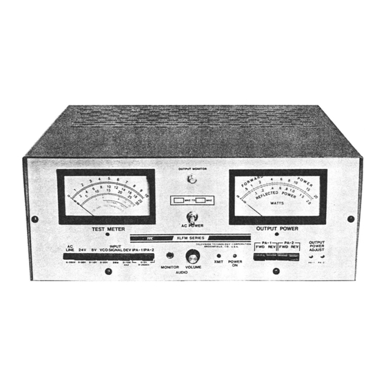
- Page 15 SECTION 2 OPERATING INSTRUCTIONS 2.1 : Controls, Switches, Indicators, Meter Positio.l~ 2.1.1: Front Panel. Refer to Figure 2.1.1 for the part location. Both the one and ten watt models have identical front panels with different silkscreen markings. FIGURE 2.1.1 XL10FM OUTPUT POWER TEST...
- Page 16 VOLUME: This control adjusts the audio level present at the monitor jack. MONITOR JACK: This is a stereo headphone jack so the incoming signal may be monitored. Only stereo headphones, such as the KOSS PRO 4 AA should be plugged into this jack.
- Page 17 Back Panel. Refer to Figure 2.1.2 for part location. 2.1. 2: FIGURE 2.1. 2 BACK PANEL C8l01 DATA Xl10 TFlANSlATOR J80' J80' SER!AL .7.• ~••. U·1.L,,, ..• .J •• I¥ (~~,..."" ••••• INPUT ___ OUTPUT OUTPUT OUHUT __ 10 WATTS 10 WATTS 75.J\.
- Page 18 i.1.3: Interior. Refer to Figure 3.1.3 for the part location. FIGURE 2.1.3 INTERIOR 0701 I ~E •••T SINI( FOR -- UNITS ONLY I 10°"" ASS'" 6900·8000 TERNlf'Ul STAr P .Q.!L 10400ULATOA I W AMP CONNECTIONS ASS'" 6900-9000 I I OR OUTPUT .••...
- Page 19 INSTALLATION Temperature and Cooling Considerations 2.2.1: The translator is designed to withstand extreme environmental abuse. However, it is obvious a translator outside on top of a telephone pole in the middle of the desert will not last as long as one inside a temperature- controlled building...
- Page 20 This is because the translator could be triggered on by unusually strong nearby stations when the desired station goes off-the-air. One way to prevent this to raise the translator's threshold adjustment; or attenuate the input signal until it is under 10000uV. 2.2.10: In booster applications it is mandatory that there is enough isolation between the receiving and transmitting antennas so that the transmitted signal...
- Page 21 2.2.14: The power amplifier is designed to withstand an infinite SWR and to put out the full rated power into a SWR as high as 2.1. Most antennas used transmitting have better than a 12dB return loss, so the worst reflected power to the translator...
- Page 23 INITIAL OPERATING PROCEDURE 2.3: 2.3.1: The following procedure is given for the initial turn on. It is pro- vided so that persons unfamiliar with the unit or even translators in general will be able to install the translator without difficulty. However, it is also important that you read Sections 2.1 and 2.2 if you are not familiar with the unit before following this procedure.
- Page 24 mended before proceeding. Remember, this unit will not operate into coat hanger, folded twin lead, or any other makeshift antenna~ must have a commercially made and properly installed transmitting antenna especially designed for the FM band. The NO. 2 FWD PWR should read lOW +lW (1 +.lW on the XLIFM) when that...
- Page 25 2.4: MODULATOR SET UP PROCEDURE 2.4.1: This procedure is to be used w~en setting the translator up for lc~~l origination. The procedure applies only to modulator equipped translators. Before proceeding, follow the initial operating procedure in Section 2.3 to ensure the translator is operating properly.
- Page 26 2.4.6: A tone decoder is included in the modu la tor boar"d the modul u tor be activated by the originating station. The tone dEcoder is set at the factory for 15 kHz. For activation, a 15 kHz +lOOHz tone at 25~ or more morl- ulation should be transmitted...
- Page 27 Triggering External Source by the Modulator 2.4.9: A set of relay contacts is brought out to TB901 at the back of the translator from the modulator board. These contacts are normally open and will close for approximately one second whenever the modulator is activated.
- Page 29 SECTION 3 THEORY OF OPERATION 3.1: GENERAL 3.1.1: Figure 3.1.1 is a block diagram of the XLIFM and the XLIOFM translator. One should also make reference to Figures 2.1.1, 2.1.2, and 2.1.3 for the loca- tion of the controls and modules. A general overview will be given...
- Page 30 -------------------------- INTERFACE METERING ASS'l' 6900-6000 POW£" CONTROL I>-~I I - - - - - - - I "=" VOlTAGE MI)NITOR =Giie L~'.;} AUDIO D'[] POwE°i m1'~o CONTOOL ~·_~-~-"'g-U-IT-'----' ~!1. ______ - __ -1 lEFT ~IGHT r----------, oPllONAl r----o AUDIO IN MOOULATOR PC l--<>...
- Page 31 CONVERSION CHART Required and Injection Frequencies Crystal To Or From 10.7 MHZ To Convert FM Channels INJECTION ABOVE FM BAND INJECTION BELOW FM BAND FM CHANNELS Crystal Injection Crystal Injection Frequency Freguency Frequency Freguency Freguency Channel 77.4 49.4 98.8 38.7 88.1 99.0 77.6...
- Page 32 CONVERSION CHART(Continuedl Required and Injection Frequencies Crystal To Or From 10.7 MHZ To Convert FM Channels FM BAND INJECTION ABOVE BELOW FM BAND INJECTION FM CHANNELS Injection Crystal Crystal Injection Frequency Freguency Frequency Frequency Frequency Channel No. 87.4 98.1 43.7 54.4 108.8 87.6...
- Page 33 3.3: Input Converter (6900-2000) 3.3.1: The input converter amplifies the input signal and mixes it down to a 10.7 MHz IF. It consists of a FET cascode amplifier followed by a FET balanced mixer. A crystal oscillator is also included within the unit. Refer to the Schematic 6900-2035.
- Page 34 3.3.10: The gates of Q205 and Q206 are tied together and are at virtual ground at both the input and IF frequency. The gate capacitance of these two devices are resonated with L213 at the LO frequency. The LO voltage present at the gates,...
- Page 35 IF AMPLIFIER PC BOARD (6900-3000) 3.4: 3.4.1: The IF amplifier PC board contains most of the amplification and filtering in the translator. The board also contains limiting to remove any AM component on the input signal. A slignal level detector is also provided with the turn-on/turn-off control circuitry.
- Page 37 PLL UPCONVERTER P.C. BOARD :3 . 5 : 3.5.1: The PLL (phase-locked loop) Upconverter P.C. Board takes the 10.7 MHz output from the IF P.C. Board and upconverts it to the output frequency. upconversion utilizes a voltage controlled oscillator (VCO) that is phase- locked to the IF input.
- Page 38 3.5.9: After the pad, the signal enters a double-balanced mixer, DBM-401, which mixes it with the local oscillator to produce a 10.7 MHz sample of the VCO. The local oscillator is supplied by a conventional crystal oscillator with a buffer amplifier. Local Oscillator 3.5.10: Q405 and its associated circuitry forms a crystal oscillator operating...
- Page 39 3.5.13: To consolidate the operation of this feedback loop; if the VCO's out- put changes in phase related to the IF input, this will cause the DC voltage at the output of IC403 to change. The output of IC402 at the collector will also change correspondingly since IC401 has no effect.
- Page 40 Modulator Operation 3.5.25: When the optional modulator activated, the MOD Turn On at P406-4 line will go to ground, causing the relay, K40l, to activate. When K40l activates R455 and R454 are shorted, causing C433 to be connected directly to IC402's output.
- Page 41 3.6: MODULATOR BOARD 3.6.1: The modulator board contains all the circuitry necessary for locally generated audio to modulate the translator's output. This includes the timing circuitry required to meet Part 74.l23l(f) of the FCC Rules and Regulations. A tone decoder is also on the board, enabling remote activation/deactivation of the modulator.
- Page 42 3.6.S: The reset pulse of the 60 minute timer is also connected to the clock input of the flip-flop IC503B. The 'Q' output of the flip-flop is normally low, but will go high when the reset pulse of the timer occurs. This will turn on Q502, activating relay K501 and the relay contacts will close.
- Page 43 3.7.2: Refer to Schematic 6900-9035. The 50mW signal from the upconverter enters at J901. Here it first passes through D901 which is a pin diode. A pin diode acts as a DC current controlled variable resistance for RF current. It's forward resistance is controlled by the feedback from the AGC loop, to be dis- cussed later.
- Page 45 10 WATT POWER AMPLIFIER 6900-S000 3.S: 3.S.1: 10 watt power amplifier amplifies the 50mW output upconverter P.C. Board (6900-4025) to the 10 watt output level. The amplifier has two stages and contains an internal AGC loop to maintain constant output power.
- Page 46 loaded by R83l. These diodes generate significant second harmonics, but since they detect 180 out of phase the harmonics produced cancel each other out. 3.8.12: The reverse power output of T804 is terminated by R8l7 and is detected by D805. 3.8.13: The detected forward power at the cathode of D806 is sent up to the metering board through R824 and the forward power calibration potentiometer,...
- Page 47 CONTROL AND METERING BOARD (6900-6000) 3.9: 3.9.1: The control and metering board contains the interconnections and meter- ing for all the subassemblies in the translator. Additionally it contains stereo demodulator and audio amplifier for the headphone jack. A peak detector monitoring deviation is also included.
- Page 48 3.10: POWER SUPPLY 3.10.1: The power supply is designed to supply 24 volts at up to 3.5 amps and -8 volts at .25 amps to the circuitry of the translator. It is of conventional design with the exception that a ferroresonant transformer is used. The supply can be powered either by 120 VAC, 60 Hz or 240 VAC 50 Hz.
- Page 49 3.13: CODE KEYER, TVK-l DRAWING 01380-2010 and 1370-8012 3.13.1: The technical description of the TVK-l Code Keyer will be broken down into the following subgroups. (Refer to Drawing Number 01380-2010.) system Clocks (3.13.2, 3.13.4 ff) set/Reset Circuitry (3.13.5 ff) Character Generator (3.13.7 ff) Outputs (3.13.14) Audio Oscillator (3.13.15 ff) Power Supply (3.13.17)
- Page 50 3.13 : CODE KEYER, TVK-1 (cont'd.) 3.13.6: When power is first applied, are discharged and act to pull up the control line of Switch Number as they charge up. This causes the output Switch 2 to go positive. Once this happens, Resistor R21 acts as a pull-up resistor to keep the output positive.
- Page 51 (cont'a.) 3.13: FIGURE 3.13-3 CMOS _____ Jo•• SWITCHES * II DIODES C:0:~ECT10N DIODE,? DIODE,? O,~~ 3 OF 10 1 05 t II DIODES DIODES 5~~~D~;>ro 5ET 7"'OF 6 OF 10 CMOS SWITCtES 3.13.11: Each set of diodes is energized by C-MOS switches which are part of IC3, or ICS.
- Page 52 3.13: CODE KEYER, TVK-1 (cont'd.) 3.13.13: Capacitor CI is used to slow down the rise time of QO. If this ca- pacitor were left out, a short duration spike would be generated when IC1 went from Q9 to QO. This to propagation delays in the carry-out line of ICI.
- Page 53 SECTION 4 MAINTENANCE AND REPAIR 4.1: GENERAL INFORMATION FCC Requirements 4.1.1: A current copy of the FCC Rules and Regulations, Volume (Part 73 and Part 74) and, in cases where antenna marking is required, Volume I (Part 17) must be available for use by the "operator in charge"...
- Page 54 4.1.7: The translator is crystal controlled and the rechanneling operation will require the replacement of the input and/or the output crystal. It is manditory, in order to ensure the translator will meet the frequency tolerance specification, to obtain the new crystals from the factory. Field rechanneling a translator under warranty will void the warranty.
- Page 55 Repairing MINIMUM RECOMMENDED Single at input frequency Signal at input frequency (may be the originating FM (may be the originating FM station) . station) . Field-strength meter or signal 75 ohm sweep generator at the lever meter capable of measur- FM band with 1 MHz harmonic ing ImV to 100mV at 10.7 MHz, markers (Wavetek Model 1061...
- Page 57 4.2: INITIAL TROUBLE SHOOTING PROCEDURE 4.2.1: In the event of trouble, the first thing is to check all the meter positions of the translator. Any significant variations from the readings given in the test data at the front of the manual should be noted.
- Page 58 If the VCO position is 11 2V, the problem resides in the output circuits. With a field-strength meter, measure the signal at the monitor output jack on the front panel. It should be 90mV ~30mV. If it isn't, the fault the PLL up- is in convertor.
- Page 59 danger here, however, is the possibility of a fault in the translator itself, causing the input signal to read inaccurately. It is still" best, though, to check the receiving array before preceding. If the input signal level is sufficient, there is still a chance that an unusually strong and close station has come on-the-air causing the input circuitry to overload.
- Page 61 INPUT CONVERTER 4.4: 4.4.1: Converter Specifications Input: Frequency Single Channel 88 - 108 MHz Return Loss 16dB typical, 12dB minimum Noise Figure 3 dB maximum Impedance Section Bandwidth 3 MHz at -3dB Section Gain 15 dB minimum Output: Frequency 10.7 MHz Impedance Return Loss 6 dB typical...
- Page 62 TABLE 4.4.1 INPUT CONVERTER VARIABLE FREQUENCY COMPONENT CHART 88 - 98 MHz 98 - 108 MHz C202 7.5 pF 8133-7R5 5.6 pF 8133-5R6 C205 8133-12RO 6.8 pF 8133-6R8 C211 8133-l5RO 8133-l2RO C214 8133-20RO 8133-l5RO C2l8 8133-130RO 8l33-l00RO C2l9 8133-l30RO 8l33-l00RO C229 8133-20RO 8133-l2RO...
- Page 63 The overall response of the input section should be similar to Figure 4.4.3. The bandwidth is determined by L208. To narrow the response, tune L208's slug out (less inductance) while compensating by adjusting C210. Tune the slug in to broaden (overcouple) the response. final response should be maximally flat or slightly overcoupled.
- Page 64 4.4.5: Output Section Alignment Switch S201 to the center position (THROUGH). Connect a 50 ohm detector to the output jack. A 50 ohm to 75 ohm transformer or pad should be used if a 75 ohm detector is used. The sweep generator attenuator should remain connected to the input jack (J201).
- Page 65 Connect a voltmeter to TP201 (see Figure 4.4.1). Measure and note the voltage measured. This should be between 1 and 4 volts. If Q205 and Q206 were replaced, then turn R206 all the way counterclockwise before measuring the voltage at TP201. Connect a high impedance voltmeter to the LO detected voltage point.
- Page 66 Input/Mixer Stage 4.4.11: To check the input section, connect a field-strength meter to J204 and switch S201 to the INPUT position. The signal should be more than 15dB higher than the input, if it is then skip to Paragraph 4.4.12. 4.4.12: The drain of 0202 should be at 20 volts.
- Page 67 IF AMPLIFIER BOARD (6900-3000) 4.5: 4.5.1: Specifications Input: Frequency 10.7 MHz Return Loss 20 dB Impedance 7dB compression point (referred to the input) 1 volt typical ® Section bandwidth (per filter) 200kHz -2dB ® 400kHz -20dB ® Optional 200kHz -3dB 400kHz ®...
- Page 68 Recommended Test Equipment List IF PC Board Repair Tab1.e - 4.5.1 TEST EQUIPMENT LIST Digital Multimeter, Fluke Model 77 or equal Field Strength Meter, Sadelco Model FSC-733B equal to measure 1 mV to 100 mV length, 50 Ohm to Alligator Clips Test Cable, RG-58/U...
- Page 69 PHASE LOCK UPCONVERTER P.C. BOARD 4.6: 4.6.1: Specifications Input: Frequency ..•... 10.7 MHz Impedance 50 ohms Signal Level O dBm minimum Output: Frequency 88 - 108 MHz Impedance 50 ohms Level 2 x +16 dBm nominal Monitor Impedance 75 ohms Monitor Level 100mV nominal LO Oscillator:...
- Page 70 Push the VCO voltage button on the front panel. The meter will read either 8 or 14 volts. Make sure there is adequate input signal to the translator. Both the input converter and the IF board must be operating properly and should be interconnected with each other.
- Page 71 J402 OUTPUT J405 J401 TP405 MONITOR \...0 MONITOR IF INPUT R409 , FM DEMOD MODULATOR BALANOE R404 FREQ DEl' BALANCE L422 OUTPUT MATCH TP402,TP403 C462 USE W/R404 L423 OUTPUT TP401 TP404 USE W R429 R460 OUTPUT LEVEL C461 R429 PHI\SE DET BALANCE L4111 TP40a...
- Page 73 4.7: MODULATOR BOARD 4.7.1 : Specifications Audio Performance: Frequency Response Z2dB 50Hz - 15kHz Total Harmonic Distortion Signal to Noise Ratio 40dB minimum Input Impedance GOO Q Zl% balanced Input Level for 75kHz deviation +3dBm nominal, adjustable +GdB Tone Decoder: Activation Frequency 15kHz...
- Page 74 TABLE 4.7.1 MINIMUM EQUIPMENT FOR RECHANNELING FM Tuner with audio outputs for connection to oscilloscope or AC voltmeter. Audio Signal Generator capable of producing 1 volt RMS into 600 ohms at 1kHz. AC voltmeter or oscilloscope. 4.7.3: Operate the translator at the original output channel frequency into a dummy load.
- Page 75 4.7.5: No Audio, Modulator Activates. This usually means the trouble is in the audio circuitry. The first thing is to ensure RS27 the MOD LEVEL control the audio is not fully counterclockwise. Connect signal generator to T901 the back of the translator. Set the generator's output level at 1 volt RMS and its frequency at 1kHz.
- Page 77 1 WATT POWER AMPLIFIER BOARD 4.8: Specifications 4.8.1: Input: Frequency 88 to 108 MHz Impedance ..•....50 ohms Return Loss 10dB typical yeP_ower +16dBm nomiIlCil Output: Power 1 watt Impedance 75 ohms Harmonics ....•..-80dB 2nd Harmonic -70dB 3rd Harmonic VSWR Capability 2:1 for 1 watt output 1 indefinate...
- Page 78 Turn the power level control down to 1 watt. I pA should be below 160mA. Disconnect the output. Push the REV PWR button for the module being tested. The power meter should read from .15 to .2 watts. Adjust R916, REV PWR TURN DOWN, if the REV PWR is outside these limits.
- Page 79 10 WATT POWER AMPLIFIER BOARD 4.9: 4.9.1: Specifications Input: Frequency 88 to 108 MHz Impedance 50 ohms Return Loss lOdB typical Drive Power +16dBm nominal Output: Power 10 watts Impedance 75 ohms Harmonics -80dB 2nd Harmonic -70dB 3rd Harmonic VSWR Capability 2:1 for 1 watt output al:l indefinate Overall:...
- Page 80 The PLL Upconverter Board should first be aligned and operating. Remove the module from the chassis and connect the antenna or dummy load to J802. Connect the driving signal from the PLL Upconverter Board to J80l. Turn the power level control on the front panel all the way up. Press the FWD power button for the module being aligned.
- Page 81 POWER SUPPLY BOARD 4.10: 4.10.1: Specifications Output Voltage +.5V, -8V +.5V Nominal Output Current ..•....24V: 3A maximum -8V: Current Limit Point 24V: 4.5A -8V: Overvoltage Trip Point +1.5V Thermal Switch Cutout Point Figure 4.10.1 POWER SUPPLY P.C. BOARD F701 FAST BLOW difJ...
- Page 82 Remove IC702 from its socket and plug P70S back in. Measure the voltage at P70l-6; if it is above +28V, Q10l is shorted. IC702 will probably be bad also. If the voltage measured step two is near zero volts, plug IC702 back in and measure the voltage at P70l-6 again.
- Page 83 4.11: CONTROL & METERING BOARD 4.11.1: Specifications Audio Monitor: Output Level ..•....3.5 volts RMS open circuit 2.5 volts RMS into 600 ohms Frequency Response 100Hz - 15kHz +3dB Nominally 2% > 19kHz Suppression 20dB Separation 26dB Deviation Monitor: Frequency Response ....•..+l, -2dB 30Hz - 75kHz Rechanneling...
- Page 84 \,!) P606 P607 P608 IC604 C603 I'M. @~~i rnrnrn ,.j~' ~ d . .. ~Jgg ~;~u 010. •.. , • ItO' P609 R628 IC602 SEP. ADJ. FIGURE 4.11.1 & CONTROL METERING BOARD...
Need help?
Do you have a question about the XLFM Series and is the answer not in the manual?
Questions and answers